Intel MFS5000SI User Guide - Page 11

List of s - server compute modules

Page 11 highlights

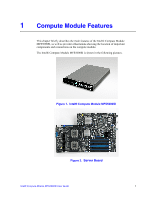
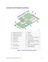
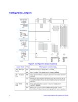
List of Figures Figure 1. Intel® Compute Module MFS5000SI 1 Figure 2. Server Board ...1 Figure 3. Component and Connector Locations 3 Figure 4. Configuration Jumper Locations 4 Figure 5. Front Panel Connectors and Indicators 5 Figure 6. Removing Top Cover 9 Figure 7. Installing Top Cover 10 Figure 8. Removing Processor Air Duct 11 Figure 9. Lifting Processor Socket Handle 12 Figure 10. Opening Load Plate 12 Figure 11. Removing Protective Shipping Cover 13 Figure 12. Orienting and Installing Processor 13 Figure 13. Removing Socket Protective Cover 14 Figure 14. Lowering Load Plate and Socket Lever 14 Figure 15. Installing Heatsink 15 Figure 16. Removing Second Processor Air Baffle 16 Figure 17. Reinstalling Processor Air Duct 17 Figure 18. Removing Processor Air Duct 18 Figure 19. Removing the Heatsink 19 Figure 20. Lifting Processor Socket Handle 19 Figure 21. Opening Load Plate 20 Figure 22. Removing Processor 20 Figure 23. Removing Protective Shipping Cover 21 Figure 24. Orienting and Installing Processor 21 Figure 25. Lowering Load Plate and Socket Lever 21 Figure 26. Re-installing Heatsink 22 Figure 27. Reinstalling Processor Air Duct 23 Figure 28. DIMM Slot Order ...25 Figure 29. Removing Processor Air Duct 26 Figure 30. Installing DIMMs...27 Figure 31. Reinstalling Processor Air Duct 28 Figure 32. Removing Processor Air Duct 29 Figure 33. Removing DIMMs...30 Figure 34. Reinstalling Processor Air Duct 31 Figure 35. Removing Screws from Server Board 32 Figure 36. Installing Standoffs for Mezzanine Card 33 Figure 37. Installing Mezzanine Card 34 Figure 38. Securing Mezzanine Card to Standoffs 35 Figure 39. Removing Screws from Mezzanine Card 36 Figure 40. Removing Mezzanine Card 37 Figure 41. Removing Standoffs 38 Figure 42. CMOS Battery Location 40 Intel® Compute Module MFS5000SI User Guide xi

  • 1
  • 2
  • 3
  • 4
  • 5
  • 6
  • 7
  • 8
  • 9
  • 10
  • 11
  • 12
  • 13
  • 14
  • 15
  • 16
  • 17
  • 18
  • 19
  • 20
  • 21
  • 22
  • 23
  • 24
  • 25
  • 26
  • 27
  • 28
  • 29
  • 30
  • 31
  • 32
  • 33
  • 34
  • 35
  • 36
  • 37
  • 38
  • 39
  • 40
  • 41
  • 42
  • 43
  • 44
  • 45
  • 46
  • 47
  • 48
  • 49
  • 50
  • 51
  • 52
  • 53
  • 54
  • 55
  • 56
  • 57
  • 58
  • 59
  • 60
  • 61
  • 62
  • 63
  • 64
  • 65
  • 66
  • 67
  • 68
  • 69
  • 70
  • 71
  • 72
  • 73
  • 74
  • 75
  • 76
  • 77
  • 78
  • 79
  • 80
  • 81
  • 82
  • 83
  • 84
  • 85
  • 86
  • 87
  • 88
  • 89
  • 90
  • 91
  • 92
  • 93
  • 94
  • 95
  • 96
  • 97
  • 98
  • 99
  • 100
  • 101
  • 102
  • 103
  • 104
  • 105
  • 106
  • 107
  • 108
  • 109
  • 110
  • 111
  • 112

IntelĀ® Compute Module MFS5000SI User Guide
xi
List of Figures
Figure 1. IntelĀ® Compute Module MFS5000SI
.........................................................................
1
Figure 2. Server Board
...............................................................................................................
1
Figure 3. Component and Connector Locations
.........................................................................
3
Figure 4. Configuration Jumper Locations
.................................................................................
4
Figure 5. Front Panel Connectors and Indicators
.......................................................................
5
Figure 6. Removing Top Cover
..................................................................................................
9
Figure 7. Installing Top Cover
..................................................................................................
10
Figure 8. Removing Processor Air Duct
...................................................................................
11
Figure 9. Lifting Processor Socket Handle
...............................................................................
12
Figure 10. Opening Load Plate
................................................................................................
12
Figure 11. Removing Protective Shipping Cover
.....................................................................
13
Figure 12. Orienting and Installing Processor
..........................................................................
13
Figure 13. Removing Socket Protective Cover
........................................................................
14
Figure 14. Lowering Load Plate and Socket Lever
..................................................................
14
Figure 15. Installing Heatsink
...................................................................................................
15
Figure 16. Removing Second Processor Air Baffle
..................................................................
16
Figure 17. Reinstalling Processor Air Duct
...............................................................................
17
Figure 18. Removing Processor Air Duct
.................................................................................
18
Figure 19. Removing the Heatsink
...........................................................................................
19
Figure 20. Lifting Processor Socket Handle
.............................................................................
19
Figure 21. Opening Load Plate
................................................................................................
20
Figure 22. Removing Processor
...............................................................................................
20
Figure 23. Removing Protective Shipping Cover
.....................................................................
21
Figure 24. Orienting and Installing Processor
..........................................................................
21
Figure 25. Lowering Load Plate and Socket Lever
..................................................................
21
Figure 26. Re-installing Heatsink
.............................................................................................
22
Figure 27. Reinstalling Processor Air Duct
...............................................................................
23
Figure 28. DIMM Slot Order
.....................................................................................................
25
Figure 29. Removing Processor Air Duct
.................................................................................
26
Figure 30. Installing DIMMs
......................................................................................................
27
Figure 31. Reinstalling Processor Air Duct
...............................................................................
28
Figure 32. Removing Processor Air Duct
.................................................................................
29
Figure 33. Removing DIMMs
....................................................................................................
30
Figure 34. Reinstalling Processor Air Duct
...............................................................................
31
Figure 35. Removing Screws from Server Board
.....................................................................
32
Figure 36. Installing Standoffs for Mezzanine Card
.................................................................
33
Figure 37. Installing Mezzanine Card
.......................................................................................
34
Figure 38. Securing Mezzanine Card to Standoffs
...................................................................
35
Figure 39. Removing Screws from Mezzanine Card
................................................................
36
Figure 40. Removing Mezzanine Card
.....................................................................................
37
Figure 41. Removing Standoffs
................................................................................................
38
Figure 42. CMOS Battery Location
..........................................................................................
40