Intel S845WD1-E Product Guide - Page 48
Replacing the Battery, With your fingertip, gently pull back the tab away from the battery.
 |
UPC - 735858159272
View all Intel S845WD1-E manuals
Add to My Manuals
Save this manual to your list of manuals |
Page 48 highlights
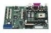
To replace the battery, follow these steps: 1. Observe the safety and ESD precautions at the beginning of this chapter. 2. Turn off all peripheral devices connected to the server. Disconnect the server's power cord from the AC power source (wall outlet or power adapter). 3. Remove the server cover. 4. Locate the battery on the board (see Figure 12). 5. With your fingertip, gently pull back the tab away from the battery. Pull out the battery. Note the orientation of the "+" and "-" on the battery. 6. Install the new battery in the connector, orienting the "-" as shown in Figure 12. 7. Replace the server cover. Figure 12. Removing the Battery TP00005 48 Intel Server Board S845WD1-E (S845WD1H) Product Guide
-
 1
1 -
2
-
3
-
4
-
5
-
6
-
7
-
8
-
9
-
10
-
11
-
12
-
13
-
14
-
15
-
16
-
17
-
18
-
19
-
20
-
21
-
22
-
23
-
24
-
25
-
26
-
27
-
28
-
29
-
30
-
31
-
32
-
33
-
34
-
35
-
36
-
37
-
38
-
39
-
40
-
41
-
42
-
 43
43 -
 44
44 -
 45
45 -
 46
46 -
 47
47 -
 48
48 -
 49
49 -
 50
50 -
 51
51 -
 52
52 -
 53
53 -
54
-
55
-
56
-
57
-
58
-
59
-
60
-
61
-
62
-
63
-
64
-
65
-
66
-
67
-
68
-
69
-
70
-
71
-
72
-
73
-
74
-
75
-
76
-
77
-
78
-
79
-
80
-
81
-
82
-
83
-
84
-
85
-
86
-
87
-
88
-
89
-
90
-
91
-
92
-
93
-
94
-
95
-
96
 |
 |

48
Intel Server Board S845WD1-E (S845WD1H) Product Guide
To replace the battery, follow these steps:
1.
Observe the safety and ESD precautions at the beginning of this chapter.
2.
Turn off all peripheral devices connected to the server.
Disconnect the server’s power cord
from the AC power source (wall outlet or power adapter).
3.
Remove the server cover.
4.
Locate the battery on the board (see Figure 12).
5.
With your fingertip, gently pull back the tab away from the battery.
Pull out the battery.
Note the orientation of the “+” and “-” on the battery.
6.
Install the new battery in the connector, orienting the “-” as shown in Figure 12.
7.
Replace the server cover.
TP00005
Figure 12.
Removing the Battery