Intel SE7230NH1 User Guide - Page 13
List of s - server board e
 |
View all Intel SE7230NH1 manuals
Add to My Manuals
Save this manual to your list of manuals |
Page 13 highlights
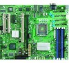
List of Figures Figure 1. Intel® Server Board SE7230NH1-E 1 Figure 2. Server Board Connector and Component Locations 4 Figure 3. DDR vs. DDR2 DIMMs 13 Figure 4. Installing DIMMs...14 Figure 5. Lift Processor Socket Lever 16 Figure 6. Lift Processor Load Plate 16 Figure 7. Removing Protective Processor Cover 17 Figure 8. Installing the Processor 17 Figure 9. Removing the Socket Protective Cover 17 Figure 10. Closing the Load Plate and Socket Lever 18 Figure 11. Installing the Active Heat Sink 19 Figure 12. Installing the Passive Heat Sink 20 Figure 13. Removing the Battery 22 Intel® Server Board SE7230NH1-E and Intel® Server Platform SR1475NH1-E User's Guide xiii
-
 1
1 -
2
-
3
-
4
-
5
-
6
-
7
-
 8
8 -
 9
9 -
 10
10 -
 11
11 -
 12
12 -
 13
13 -
 14
14 -
 15
15 -
 16
16 -
 17
17 -
 18
18 -
19
-
20
-
21
-
22
-
23
-
24
-
25
-
26
-
27
-
28
-
29
-
30
-
31
-
32
-
33
-
34
-
35
-
36
-
37
-
38
-
39
-
40
-
41
-
42
-
43
-
44
-
45
-
46
-
47
-
48
-
49
-
50
-
51
-
52
-
53
-
54
-
55
-
56
-
57
-
58
-
59
-
60
-
61
-
62
-
63
-
64
-
65
-
66
-
67
-
68
-
69
-
70
-
71
-
72
-
73
-
74
-
75
-
76
-
77
-
78
-
79
-
80
-
81
-
82
-
83
-
84
-
85
-
86
-
87
-
88
-
89
-
90
 |
 |

Intel
®
Server Board SE7230NH1-E and Intel
®
Server Platform SR1475NH1-E User’s Guide
xiii
List of Figures
Figure 1. Intel
®
Server Board SE7230NH1-E
.............................................................................
1
Figure 2. Server Board Connector and Component Locations
..................................................
4
Figure 3. DDR vs. DDR2 DIMMs
..............................................................................................
13
Figure 4. Installing DIMMs
........................................................................................................
14
Figure 5. Lift Processor Socket Lever
......................................................................................
16
Figure 6. Lift Processor Load Plate
..........................................................................................
16
Figure 7. Removing Protective Processor Cover
.....................................................................
17
Figure 8. Installing the Processor
.............................................................................................
17
Figure 9. Removing the Socket Protective Cover
....................................................................
17
Figure 10. Closing the Load Plate and Socket Lever
...............................................................
18
Figure 11. Installing the Active Heat Sink
.................................................................................
19
Figure 12. Installing the Passive Heat Sink
..............................................................................
20
Figure 13. Removing the Battery
..............................................................................................
22