Intel SE7230NH1 User Guide - Page 20
Connector and Header Locations - e lx
 |
View all Intel SE7230NH1 manuals
Add to My Manuals
Save this manual to your list of manuals |
Page 20 highlights
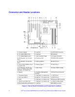
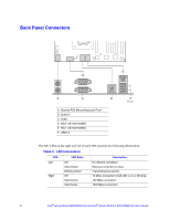
Connector and Header Locations AB C D E F GH I J K L M N O P Q MM LL KK JJ II HH BB Y W U GG FF EE DD CC AA Z X V T SR TP01781 A. Intrusion Header N. SysFan1 B. PCI (32bit/33MHz) Slot 1 O. SysFan2 C. PCI (32bit/33MHz) Slot 2 P. 2x4 Processor Power D. PCI Express* x4 (x1 Lane) Slot 3 Q. Processor Fan E. PCI Express* x8 (x4 Lane) Slot 4 R. Memory Bank 2 F. PCI-X (64bit/100MHz) Slot 5 - S. Memory Bank 1 LX version only G. PCI Express* x8 (x8 Lane) Slot 6 - LC version only; Riser Card Slot - LX version only T. Main Power H. Battery U. Hardware Management Controller I. Processor Socket V. SysFan8 - LX version only J. NIC1 and USB1-2 W. SysFan7 - LX version only K. NIC2 X. SysFan6 - LX version only L. Serial A and Video Port Y. SysFan5 - LX version only M. PS2 Stacked Mouse/Keyboard Z. SysFan4 AA.PATA IDE Connector BB.SysFan3 CC.Floppy Connector DD.SCSI LED Connector EE.SATA Port 3 FF.SATA Port 2 GG.Clear CMOS Jumper HH.Front Panel Connector II. SATA Port 1 JJ.SATA Port 0 KK.External USB Connector LL.CMOS Config Jumper MM.HSBP Connector Figure 2. Server Board Connector and Component Locations 4 Intel® Server Board SE7230NH1-E and Intel® Server Platform SR1475NH1-E User's Guide
-
 1
1 -
2
-
3
-
4
-
5
-
6
-
7
-
8
-
9
-
10
-
11
-
12
-
13
-
14
-
 15
15 -
 16
16 -
 17
17 -
 18
18 -
 19
19 -
 20
20 -
 21
21 -
 22
22 -
 23
23 -
 24
24 -
 25
25 -
26
-
27
-
28
-
29
-
30
-
31
-
32
-
33
-
34
-
35
-
36
-
37
-
38
-
39
-
40
-
41
-
42
-
43
-
44
-
45
-
46
-
47
-
48
-
49
-
50
-
51
-
52
-
53
-
54
-
55
-
56
-
57
-
58
-
59
-
60
-
61
-
62
-
63
-
64
-
65
-
66
-
67
-
68
-
69
-
70
-
71
-
72
-
73
-
74
-
75
-
76
-
77
-
78
-
79
-
80
-
81
-
82
-
83
-
84
-
85
-
86
-
87
-
88
-
89
-
90
 |
 |
