Intel SE7320VP2 User Guide - Page 24
Power Supply, Optional Hardware, Storage Devices
 |
View all Intel SE7320VP2 manuals
Add to My Manuals
Save this manual to your list of manuals |
Page 24 highlights
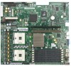
Server Board Features For memory on-line sparing, one DIMM per channel is used as the memory spare. The spare DIMM is not available for use, but is kept in reserve. If a DIMM begins to fail, the content of the failing DIMM is copied to the spare DIMM in that channel. When all of the data is copied to the spare DIMM, the primary DIMM is removed from service and the spare DIMM takes its place. When memory on-line sparing is used, the spare DIMMs must be equal to or larger than the largest in-service DIMM in that channel. ✏ NOTE Memory mirroring and memory sparing are mutually exclusive. Only one can be active at a time. Refer to the Intel® Server Board SE7320VP2 Technical Product Specification for additional information regarding the memory sub-system. Power Supply A minimum of 450 Watts is required. Your supply must provide a minimum of 1.2 A of 5 V standby current or the board will not boot. Use the power budget tool to determine the minimum power supply for your system, based on all installed components. For a link to the power budget utility, see "Additional Information and Software." Optional Hardware Storage Devices The Server Board SE7320VP2 provides two SATA connections and two ATA (IDE/ATAPI) controllers. The two SATA connectors are on the powersupply side of the board marked "SATA 0" and "SATA 1". Each ATA connection supports one or two ATA/100 devices. IDE devices can be connected to the standard ATA connector, next to the floppy connector, or to the 100-pin cable connector. A floppy drive connection is available through the standard floppy connector or through the 100pin front panel connector if you have installed the optional hot-swap backplane. Drive power is supplied from the chassis power supply for conventional cable-attached drives. Power is available from the IDE power header near the cutout in the center on the power supply side of the board for ATA-compliant IDE flash drives (mini IDE, iDiskOnChip*, and others). For multiple slimline devices a Y-cable for power can be used. For direct-plug IDE flash drives, use the AXXFLASHPWR accessory cable. See the documentation included with your server chassis for additional drive information and drive installation instructions. 24
-
 1
1 -
2
-
3
-
4
-
5
-
6
-
7
-
8
-
9
-
10
-
11
-
12
-
13
-
14
-
15
-
16
-
17
-
18
-
 19
19 -
 20
20 -
 21
21 -
 22
22 -
 23
23 -
 24
24 -
 25
25 -
 26
26 -
 27
27 -
 28
28 -
 29
29 -
30
-
31
-
32
-
33
-
34
-
35
-
36
-
37
-
38
-
39
-
40
-
41
-
42
-
43
-
44
-
45
-
46
-
47
-
48
-
49
-
50
-
51
-
52
-
53
-
54
-
55
-
56
-
57
 |
 |
