Intel SRCU42L User Guide - Page 17
Diagnostic Features
 |
UPC - 735858157872
View all Intel SRCU42L manuals
Add to My Manuals
Save this manual to your list of manuals |
Page 17 highlights
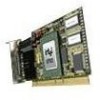
Hardware Installation Table 2-1. Controller Jumper Settings Jumper Block J1 Jumper Position Jumper on A No jumper on A Jumper on B No jumper on B Jumper on pins [1-2] J4 Jumper on pins [2-3] No jumpers Jumper on A No jumper on A J5 Jumper on B No jumper on B Definition Termination for channel A is on. Termination for channel A is off. Termination for channel B is on. Termination for channel B is off. IOP is in reset mode with firmware recovery enabled. IOP is in normal run mode. IOP is in normal run mode. Controller supplies termination power to channel A. Controller does not supply termination power to channel A. Controller supplies termination power to channel B. Controller does not supply termination power to channel B. 2.2 J1 - SCSI bus termination jumper block. These jumpers control SCSI termination for both channels. J4 - IOP mode select jumper block: This jumper is used to place the IOP in reset, which enables the flash chip to be programmed to recover resident firmware. See Appendix A for a detailed description of jumper J4. J5 - SCSI termination power jumper block - At least one device has to supply +5 volts termination power to the SCSI bus. Diagnostic Features The SRCU42L has LED indicators, an 80db audible alarm, and boot-up beep sequences that can help diagnose the controller. Hardware Installation and User's Guide 17
-
 1
1 -
2
-
3
-
4
-
5
-
6
-
7
-
8
-
9
-
10
-
11
-
 12
12 -
 13
13 -
 14
14 -
 15
15 -
 16
16 -
 17
17 -
 18
18 -
 19
19 -
 20
20 -
 21
21 -
 22
22 -
23
-
24
-
25
-
26
-
27
-
28
-
29
-
30
-
31
-
32
-
33
 |
 |
