Intel SSR212MC2 Hardware Technical Product Specification - Page 24
Front/Rear Panel Controls and Indicators
 |
UPC - 735858199094
View all Intel SSR212MC2 manuals
Add to My Manuals
Save this manual to your list of manuals |
Page 24 highlights
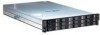
Feature Summary Intel® Storage Server SSR212MC2 1.9.1 Front/Rear Panel Controls and Indicators The front/rear panel controls and indicators are defined below: On/Off Switch (front mounted) System Reset (front mounted) ID LED Switch (front & rear mounted) NMI (rear mounted) Power Active Unit Fault ID LED Table 7: Front/Rear Control Button Functions Toggles the system power on and off. Reboots the system. Illuminates the blue system identification LED. Non Maskable Interrupt. Table 8: Front LED Indicator Status Continuous green light indicates the system has power applied to it. No light indicates the system does not have power applied to it (other than 5 V standby power). Continuous amber light indicates fault present. The blue system identification LED is used to help identify a system for servicing. This is especially useful when the system is installed within a high density rack or cabinet that is populated with several similar systems. Figure 9: Front Panel 16 Revision 1.2
-
 1
1 -
2
-
3
-
4
-
5
-
6
-
7
-
8
-
9
-
10
-
11
-
12
-
13
-
14
-
15
-
16
-
17
-
18
-
 19
19 -
 20
20 -
 21
21 -
 22
22 -
 23
23 -
 24
24 -
 25
25 -
 26
26 -
 27
27 -
 28
28 -
 29
29 -
30
-
31
-
32
-
33
-
34
-
35
-
36
-
37
-
38
-
39
-
40
-
41
-
42
-
43
-
44
-
45
-
46
-
47
 |
 |
