Intel SSR212MC2 Hardware Technical Product Specification - Page 6
List of s - power supply
 |
UPC - 735858199094
View all Intel SSR212MC2 manuals
Add to My Manuals
Save this manual to your list of manuals |
Page 6 highlights
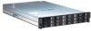
List of Figures Intel® Storage Server SSR212MC2 TPS List of Figures Figure 1. Intel® Storage Server SSR212MC2 1 Figure 2. Intel® Storage Server SSR212MC2R Block Diagram 5 Figure 3. Intel® Storage Server SSR212MC2 Block Diagram 6 Figure 4. System Components ...7 Figure 5: Vitesse* VSC410 Block Diagram 11 Figure 6: PMC* PM8388 Block Diagram 12 Figure 7: Back Panel I/O Ports 15 Figure 8: Chassis Front and Rear 16 Figure 9: Front Panel ...17 Figure 10: Rack Mounting...18 Figure 11: Power Supply Module 20 Figure 12: Cooling Module...22 Figure 13: Drive Carrier Removal 23 Figure 14: Hard Disk Drive Bays 25 Figure 15: Hard Drive Carrier Assembly 26 vi Revision 1.2
-
 1
1 -
 2
2 -
 3
3 -
 4
4 -
 5
5 -
 6
6 -
 7
7 -
 8
8 -
 9
9 -
 10
10 -
 11
11 -
 12
12 -
13
-
14
-
15
-
16
-
17
-
18
-
19
-
20
-
21
-
22
-
23
-
24
-
25
-
26
-
27
-
28
-
29
-
30
-
31
-
32
-
33
-
34
-
35
-
36
-
37
-
38
-
39
-
40
-
41
-
42
-
43
-
44
-
45
-
46
-
47
 |
 |

List of Figures
Intel® Storage Server SSR212MC2
TPS
vi
Revision 1.2
List of Figures
Figure 1. Intel® Storage Server SSR212MC2
..............................................................................
1
Figure 2. Intel® Storage Server SSR212MC2R Block Diagram
...................................................
5
Figure 3. Intel® Storage Server SSR212MC2 Block Diagram
......................................................
6
Figure 4. System Components
.....................................................................................................
7
Figure 5: Vitesse* VSC410 Block Diagram
.................................................................................
11
Figure 6: PMC* PM8388 Block Diagram
.....................................................................................
12
Figure 7: Back Panel I/O Ports
...................................................................................................
15
Figure 8: Chassis Front and Rear
...............................................................................................
16
Figure 9: Front Panel
..................................................................................................................
17
Figure 10: Rack Mounting
...........................................................................................................
18
Figure 11: Power Supply Module
................................................................................................
20
Figure 12: Cooling Module
..........................................................................................................
22
Figure 13: Drive Carrier Removal
...............................................................................................
23
Figure 14: Hard Disk Drive Bays
.................................................................................................
25
Figure 15: Hard Drive Carrier Assembly
.....................................................................................
26