Invacare 9SL Owners Manual - Page 86
Installing Amputee Bracket, Super Hemi Models, SL/XT
 |
View all Invacare 9SL manuals
Add to My Manuals
Save this manual to your list of manuals |
Page 86 highlights
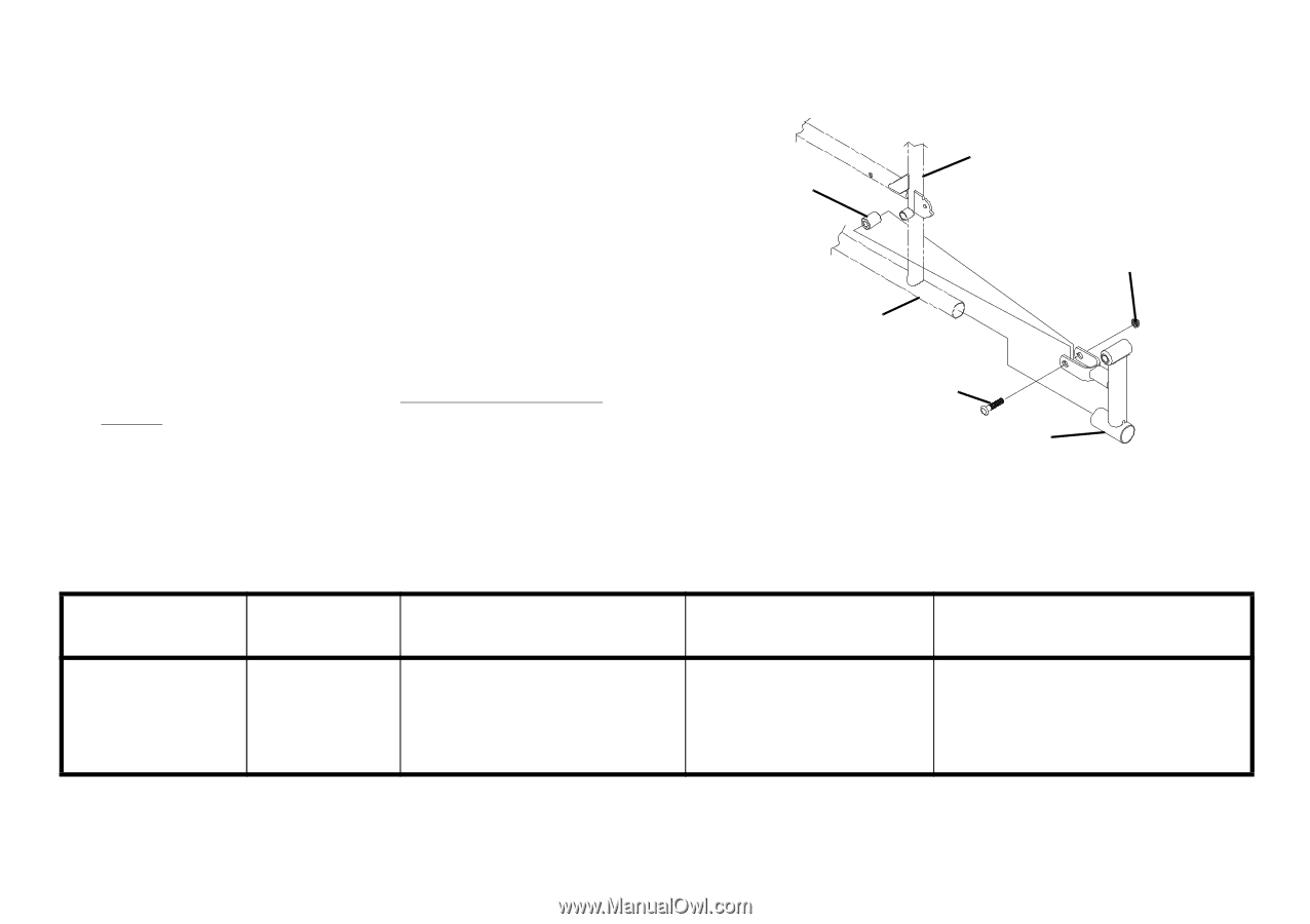
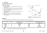
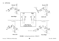
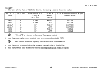
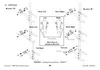
12 OPTIONS Installing Amputee Bracket Super Hemi Models 1. Remove the plug button or anti-tipper from the step tube of the wheelchair frame. 2. Slide the amputee attachment over the step tube of the wheelchair. 3. Secure the amputee attachment to the wheelchair with the hew screw, spacer and locknut. 4. Reinstall the plug button or anti-tipper onto the step tube of the wheelchair frame. 5. Repeat STEPS 1-4 for the opposite side of the wheelchair. 6. Reposition the rear wheels. Refer to Removing/Installing Rear Wheels on page 55. Spacer Wheelchair Frame Step Tube Hex Screw Amputee Bracket Locknut FIGURE 3 Installing Amputee Bracket 9000SL/XT 1. Refer to the following chart or FIGURE 4 to determine the mounting position of the amputee bracket: SEAT-TO-FLOOR *BRACKET ADULT A ADULT B HEMI B HEMI A AXLE SPACER POSITION (ON BRACKET) DOWN DOWN UP UP SIDE OF WHEELCHAIR RIGHT LEFT RIGHT LEFT * "A" and "B" are stamped on the sides of the amputee bracket. AXLE MOUNTING POSITION (ON WHEELCHAIR) TOP TOP BOTTOM BOTTOM Invacare® 9000 Series Wheelchair 86 Part No. 1056953
-
 1
1 -
2
-
3
-
4
-
5
-
6
-
7
-
8
-
9
-
10
-
11
-
12
-
13
-
14
-
15
-
16
-
17
-
18
-
19
-
20
-
21
-
22
-
23
-
24
-
25
-
26
-
27
-
28
-
29
-
30
-
31
-
32
-
33
-
34
-
35
-
36
-
37
-
38
-
39
-
40
-
41
-
42
-
43
-
44
-
45
-
46
-
47
-
48
-
49
-
50
-
51
-
52
-
53
-
54
-
55
-
56
-
57
-
58
-
59
-
60
-
61
-
62
-
63
-
64
-
65
-
66
-
67
-
68
-
69
-
70
-
71
-
72
-
73
-
74
-
75
-
76
-
77
-
78
-
79
-
80
-
 81
81 -
 82
82 -
 83
83 -
 84
84 -
 85
85 -
 86
86 -
 87
87 -
 88
88 -
 89
89 -
 90
90 -
 91
91 -
92
 |
 |