JVC UX-EP25 Instruction Manual - Page 3
For U.S.A., For the main unit, Note to CATV system installer, For Canada/pour le Canada, G-2 - sp
 |
View all JVC UX-EP25 manuals
Add to My Manuals
Save this manual to your list of manuals |
Page 3 highlights
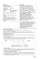
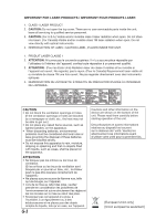
(For U.S.A.) For the main unit: Declaration of Conformity Model Number: UX-EP25 Trade Name: JVC Responsible Party: JVC Americas Corp. Address: 1700 Valley Road, Wayne New Jersey 07470 Telephone Number: 973-317-5000 This device complies with Part 15 of FCC Rules. Operation is subject to the following two conditions: (1) This device may not cause harmful interference, and (2) this device must accept any interference received, including interference that may cause undesired operation. (For U.S.A.) Note to CATV system installer: This reminder is provided to call the CATV system installer's attention to section 82040 of the NEC which provides guidelines for proper grounding and, in particular, specifies that the cable ground shall be connected to the grounding system of the building, as close to the point of cable entry as practical. For Canada/pour le Canada THIS DIGITAL APPARATUS DOES NOT EXCEED THE CLASS B LIMITS FOR RADIO NOISE EMISSIONS FROM DIGITAL APPARATUS AS SET OUT IN THE INTERFERENCE-CAUSING EQUIPMENT STANDARD ENTITLED "DIGITAL APPARATUS," ICES-003 OF THE DEPARTMENT OF COMMUNICATIONS. CET APPAREIL NUMERIQUE RESPECTE LES LIMITES DE BRUITS RADIOELECTRIQUES APPLICABLES AUX APPAREILS NUMIRIQUES DE CLASSE B PRESCRITES DANS LA NORME SUR LE MATERIEL BROUILLEUR; "APPAREILS NUMERIQUES", NMB003 EDICTEE PAR LE MINISTRE DES COMMUNICATIONS. Caution: Proper Ventilation To avoid risk of electric shock and fire, and to prevent damage, locate the apparatus as follows: 1.Front: No obstructions and open spacing. 2.Sides/ Top/ Back: No obstructions should be placed in the areas shown by the dimensions below. 3.Bottom: Place on the level surface. Maintain an adequate air path for ventilation by placing on a stand with a height of 10 cm (3-15/16") or more. Attention: Aération correcte Pour prévenir tout risque de décharge électrique ou d'incendie et éviter toute détérioration, installez l'appareil de la manière suivante: 1.Avant: Bien dégagé de tout objet. 2.Côtés/dessus/dessous: Assurez-vous que rien ne bloque les espaces indiqués sur le schéma ci-dessous. 3.Dessous: Posez l'appareil sur une surface plane et horizontale. Veillez à ce que sa ventilation correcte puisse se faire en le plaçant sur un support d'au moins dix centimètres de hauteur. Front Face 15 cm (5-15 /16 ") 2 cm (13/16 ") 15 cm (5-15 /16 ") 2 cm (13/16 ") 15 cm (5-15 /16 ") 15 cm (5-15 /16 ") 15 cm (5-15 /16 ") Side Côté SP-UXEP25 CA-UXEP25 SP-UXEP25 10 cm (3-15 /16 ") CA-UXEP25 * About the cooling fan A cooling fan is mounted on the right side of the unit to prevent abnormal temperature inside the unit, thus assuring normal operation of the unit. The cooling fan automatically starts rotating to intake external cool air when the volume is increased up to more than a certain level. * À propos du ventilateur de refroidissement Un ventilateur de refroidissement se trouve sur le panneau arrière de l'appareil afin d'éviter la création d'une température anormale à l'intérieur de l'appareil et permettre ainsi un fonctionnement normal de l'appareil. Le ventilateur de refroidissement commence à tourner et à aspirer de l'air frais automatiquement quand le volume est augmenté au-dessus d'un certain niveau. G-2
-
 1
1 -
 2
2 -
 3
3 -
 4
4 -
 5
5 -
 6
6 -
 7
7 -
 8
8 -
 9
9 -
10
-
11
-
12
-
13
-
14
-
15
-
16
-
17
-
18
-
19
-
20
-
21
-
22
-
23
-
24
-
25
-
26
-
27
-
28
-
29
-
30
-
31
-
32
-
33
-
34
-
35
 |
 |