JVC V25U Instruction Manual - Page 15
Connecting to the AC 24 V power supply, Power cord - vn manual
 |
View all JVC V25U manuals
Add to My Manuals
Save this manual to your list of manuals |
Page 15 highlights
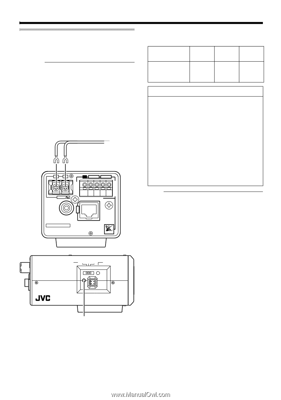
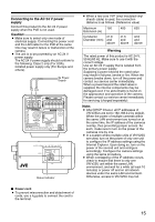
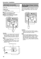
Connecting to the AC 24 V power supply Connect this product to the AC 24 V power supply when the PoE is not used. Caution: ● Make sure to select only one mode of electrical supply. Connecting the power cord and the LAN cable for the PoE at the same time may result in failure or malfunction of the camera. ● The unit is to be powered by an AC 24 V power supply. The AC 24 V power supply should conform to the following: Class 2 only (For USA), Isolated power supply only (For Europe and others). To Power Supply OUTPUT CLASS 2 ONLY FOR USA ISOLATED POWER ONLY FOR EUROPE AND OTHER 1 2 G2 12 1 INPUT AC24V ALARM PoE MONITOR OUT 10BASE-T/ SEE INSTRUCTION MANUAL 100BASE-TX CAUTION: NEVER USE PoE AND AC 24V AT THE SAME TIME DO NOT CONNECT TO THE TELEPHONE NETWORK PUSH MONITOR OUT PAL OFF NTSC RESET STATUS IRIS Status Indicator ● When a two-core VVF (vinyl insulated vinyl sheath cable) is used, the connection distance is as follows. (Reference value) Maximum 150 400 630 Extension (m) Conductor R1.0 Diameter (mm) and above R1.6 and above R2.0 and above Warning The rated power of this product is AC 24 V, 50 Hz/60 Hz. Make sure to use it with the correct voltage. Use an AC 24 V supply that is isolated from the primary power supply. Supplying a power beyond the rated value may result in failures, smoke or fire. When the camera breaks down, turn off the power and contact our service center immediately. When a power beyond the rated value is supplied, the internal components may be damaged even if no abnormality is found on the appearance and operation of the camera. Please contact our service center immediately for servicing (charged separately). Note: ● After DHCP timeout, all IP addresses of VN-V25Us are set to 192.168.0.2 by default. When the power of multiple cameras within the same LAN environment are turned on at the same time, the IP address of the cameras overlap, thus preventing proper access. As such, make sure to turn on the power of the cameras one by one. ● In a system where multiple units of VN-V25U are used, turn on the power of only one unit to configure the IP address settings using the Internet Explorer. Upon doing so, turn on the power of the second unit and configure accordingly. Configure the camera settings using the same procedure. ● When overlapping of the IP address occurs, check to ensure that there is only one VN-V25U unit within the same LAN environment, and wait for a while (at least 10 minutes) or power off and on all network devices under the same LAN environment. Otherwise, access to VN-V25U may fail. ⅷ Power cord ● To prevent misconnection and detachment of cords, use a lug plate to connect the cord to the terminal. 15
-
 1
1 -
2
-
3
-
4
-
5
-
6
-
7
-
8
-
9
-
 10
10 -
 11
11 -
 12
12 -
 13
13 -
 14
14 -
 15
15 -
 16
16 -
 17
17 -
 18
18 -
 19
19 -
 20
20 -
21
-
22
-
23
-
24
-
25
-
26
-
27
-
28
-
29
-
30
-
31
-
32
-
33
-
34
-
35
-
36
-
37
-
38
-
39
-
40
-
41
-
42
-
43
-
44
-
45
-
46
-
47
-
48
-
49
-
50
-
51
-
52
-
53
-
54
-
55
-
56
-
57
-
58
-
59
-
60
-
61
-
62
-
63
-
64
-
65
-
66
-
67
-
68
-
69
-
70
-
71
-
72
-
73
-
74
-
75
-
76
-
77
-
78
-
79
-
80
-
81
-
82
-
83
-
84
-
85
-
86
-
87
-
88
-
89
-
90
-
91
-
92
 |
 |