JVC V25U Instruction Manual - Page 16
LAN Cable Connection, Monitor Signal Output Terminal Connection - vn -
 |
View all JVC V25U manuals
Add to My Manuals
Save this manual to your list of manuals |
Page 16 highlights
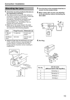
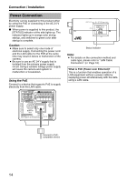
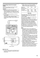
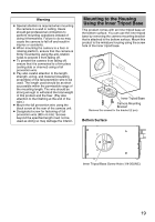
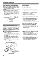
Connection / Installation LAN Cable Connection Connect the camera to a hub or computer using a LAN cable. Cable to use ● Shielded cable ● Length of 100 m or shorter Ⅵ When connecting to a hub Make use of a straight cable. Ⅵ When connecting to a computer Make use of a cross cable. 1 2 G2 12 1 OUTPUT INPUT AC24V ALARM Monitor Signal Output Terminal Connection This terminal is used for adjusting the camera angle during installation. Connect it to devices such as a video monitor using a video cable (RCA). 1 2 G2 12 1 OUTPUT INPUT CLASS 2 ONLY FOR USA ISOLATED POWER ONLY FOR EUROPE AND OTHER AC24V ALARM PoE MONITOR OUT 10BASE-T/ SEE INSTRUCTION MANUAL 100BASE-TX CAUTION: NEVER USE PoE AND AC 24V AT THE SAME TIME DO NOT CONNECT TO THE TELEPHONE NETWORK PUSH PoE CLASS 2 ONLY FOR USA ISOLATED POWER ONLY FOR EUROPE AND OTHER MONITOR OUT 10BASE-T/ SEE INSTRUCTION MANUAL 100BASE-TX CAUTION: NEVER USE PoE AND AC 24V AT THE SAME TIME DO NOT CONNECT TO THE TELEPHONE NETWORK PUSH Caution: ● However, cross cables cannot be used with some computer models. When connecting VN-V25U directly to a computer, check the computer's LAN specifications in advance. Note: ● Make use of a Category 5 (or higher) cable when 100BASE-TX is used. ● To distribute images to the network, set the [MONITOR OUT] switch at the side of this product to AOFFB. [MONITOR OUT] Switch Caution: ● A longer cable extension distance causes signals to be attenuated, image resolution to deteriorate and noise to increase. Note: ● Select the signal system for the monitor output using the [MONITOR OUT] switch at the side of this product. (ANTSCB or APALB) After adjusting the camera angle, set the switch to AOFFB. After changing the switch settings, press the Reset button to reboot the camera. MONITOR OUT PAL OFF NTSC RESET STATUS IRIS 16
-
 1
1 -
2
-
3
-
4
-
5
-
6
-
7
-
8
-
9
-
10
-
 11
11 -
 12
12 -
 13
13 -
 14
14 -
 15
15 -
 16
16 -
 17
17 -
 18
18 -
 19
19 -
 20
20 -
 21
21 -
22
-
23
-
24
-
25
-
26
-
27
-
28
-
29
-
30
-
31
-
32
-
33
-
34
-
35
-
36
-
37
-
38
-
39
-
40
-
41
-
42
-
43
-
44
-
45
-
46
-
47
-
48
-
49
-
50
-
51
-
52
-
53
-
54
-
55
-
56
-
57
-
58
-
59
-
60
-
61
-
62
-
63
-
64
-
65
-
66
-
67
-
68
-
69
-
70
-
71
-
72
-
73
-
74
-
75
-
76
-
77
-
78
-
79
-
80
-
81
-
82
-
83
-
84
-
85
-
86
-
87
-
88
-
89
-
90
-
91
-
92
 |
 |
