Kenmore 33094 Owners Manual - Page 21
Removing, the Burner, Door Assembly, Ultra Low NOx Natural, Gas Burner
 |
View all Kenmore 33094 manuals
Add to My Manuals
Save this manual to your list of manuals |
Page 21 highlights
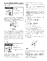
Removing the Burner Door Assembly 1. Turn offthe gas to the water heater at the manual gas shut-off valve (Figure 3). 2. Turn the gas control knob on the combination gas control valve/thermostat clockwise to the "OFF" position (Figure 1). NOTE: Depress the dial stopon Robertahawvalve before turning the gas control knob. See Lighting Instructions on the water heater. 3. Remove the outer door. 4. Remove the two screws eecudng the burner door assembly to the combustion chamber. (Figure 24). GAS VALVE/ THERMOSTAT Ultra Low NOx Natural Gas Burner Check the burner to see if it is dirty or clogged. The burner may be cleaned with soft paint brush (Figure 26). Do not use a wire brush or any tool that may damage the burner screen. Important: Do not use the bumer if the bumer screen is damaged. NOTE: Damage may be rips or holes in the burner screen. Discoloration is normal. MANIFOLD TUBE PIEZO IGNITER BUTTON - PILOT TUBE BURNER _ ) - BURNER DOOR DOOR SCREW (2) TWO PIECE WlRE CONNECTOR FIGURE 26, Replacing the Pilot Assembly FIGURE 24. 5. Disconnect the thermocouple (right-hand thread), pilot tube, the igniter wire from the igniter button, and manifold tube at the thermostat. (Figure 25). 6, Grasp the manifoldtube and push down slightly to free the manifold tube, pilot tube, and thermocouple. 7. Carefully remove the burner door assembly from the combustion chamber. Be sure not to damage internal parts. ROBERTSHAW GAS VALVE _ _ _--PILOTTUBE THERMeeOURLE ._EJ MANIFOLD TUBE j'_ FIGURE 25. 1. Follow the instructionsin =Removing the Burner Door Assembly" section t_ remove the assembly. 2. Remove the retainerdip secudngthe two p_,ce wire connector to the burnerdoorassembly.(Notethe orientation ofthe retainerclip).Insertthe tip of a large fiat head screwdriverbetween the dip and the top of the two piece wire connector.Carefullyrotatethe screwdriverto raise the clip. It may be necessaryto removethe connector one side at a time. (See Figure27.) 3, Locatewhere the thermocouple connects tothe rear of the pilotassembly,and pullthe thermocouple tip from the rear of the pilotassembly. 4. Remove the nut secudng the pilot assembly to the burner and keep it for rouse later. 5. Use a 1/2" open end wrench, to loosen the nut secuhng the pilot tube to the pilot. To prevent any bending use a pair of pliers to steady the pilot bracket. 6. Remove the aid pilot assembly (including the igniterwire) from the burner door assembly. 7. Insertthe pilot tube intothe new pilot assembly, Important The new pilot assemblycomes with an odflce. This ohfice must be installed when replacing the pilot assembly, IMPORTANT: Do not operate this water heatar without the orifice in place. 8, Use a 1/2"open end wrench,to tightenthe nut secodngthe pilot tube to the pilot. To prevent any bending use a pair of pliersto steadythe pilotbracket. 9. Use the nut removed in a previousstep to securethe new pilot assemblyto the burner. 10. Insert the igniterwire throughthe burnerdoor and reconnect the thermocoupleto the pilotassembly. See =Replacingthe Thermceeuple"section. 11. Reinstallthe two piecewire connector. NOTE: The pilot tube mustbe at the topfollowedbythe igniterwire then the thermocouple. 12. Followthe instructionsin =Replacingthe BumerDoor Assembly" sectionto reinstallthe assembly. 21
-
 1
1 -
2
-
3
-
4
-
5
-
6
-
7
-
8
-
9
-
10
-
11
-
12
-
13
-
14
-
15
-
 16
16 -
 17
17 -
 18
18 -
 19
19 -
 20
20 -
 21
21 -
 22
22 -
 23
23 -
 24
24 -
 25
25 -
 26
26 -
27
-
28
-
29
-
30
-
31
-
32
 |
 |
