Kenmore 3314 Owners Manual - Page 13
usedwitha non-potable
 |
View all Kenmore 3314 manuals
Add to My Manuals
Save this manual to your list of manuals |
Page 13 highlights
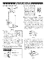
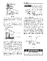
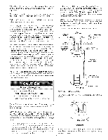
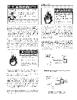
Thiswatehr eatesrhalnl otbeconnectetodanyheatinsgystems or component(su)sedwitha non-potablweaterheating appliance. Allpipingcomponenctosnnectetodthisuniftorspaceheating applicationshsalbl esuitableforusewithpotablwe ater. Toxicchemicalssu, chasthoseusedforboiletrreatmensthall notbeintroduceindtothissystem. Watesrupplysystemms ay,becausoefsucheventsashigh linepressurfer,equenctut-offosrtheeffectosfwaterhammer amongothers,haveinstalleddevicessuchas pressure reducinvgalvesc,heckvalvesb, ackflowpreventerest,c.to controthl esetypesofproblemsW. henthesedeviceasrenot equippewdithaninternably-pasas,ndnoothemr easureasre takent,hedevicecsausethewatersystemtobeclosedA. s wateris heatedit, expand(sthermaelxpansiona)ndclosed systemdsonotallowfortheexpansioonfheatewd ater. Thewatewr ithinthewaterheatetrankexpandassitisheated andincreasethsepressuroefthewatesrystemI.ftherelieving poinot fthewaterheatert'semperature-presrseulireevf alveis reachedt,hevalvewill relievetheexcesspressure.The temperature-pressruerleiefvalveis notintendedfor the constanrteliefof thermael xpansionT.hisisanunacceptable conditioanndmustbecorrectedIt.is recommendtheadtany deviceisnstallewdhichcouldcreatea closedsystemhavea by-pasasnd/otrhesystemhaveanexpansiotannkto relieve thepressurbeuiltbythermaelxpansiointhewatersystem. RefetrotheTheTma! Expar_sion section under Troubleshooting Guide or contact local plumbing authority or local Sears Service Center on how to control this situation. Lookatthetopofthewatehr eaterT.hecoldwaterinletis marke'dCOLD"P.utwoorthreeturnsofteflontapearound thethreadedendof thethreaded-to-swceoaut plingand aroundbothendsofthe3/4"NPTthreadendippleU. sing flexibleconnectorcso,nnectht ecoldwaterpipetothecold waterinleot fthewatehr eater. NOTE: This water heater is super insulated to minimize heat moss from the tank. Further reduction in heat loss can be accomplished by insulating the hot water lines from the water heater. INSTALLATION COMPLETED USING INSTALLATION KIT HOT WATER OUTLET FLEXIBLE WATER CONNECTORS COLD WATER INLET l THREADED TO l SHVUATLVOEFF THREADED TO DRAFT HOOD TEMPRPEERSSAUTURREERELIEF VALVE NOTE: To protect against untimely corrosion of hot and cold water fittings, it is strongly recommended that dioelectric unions or couplings be installed on this water heater when connected to copper pipe. Property Damage Hazard . Avoid water heater damage. Install thermal expansion tank if necessary, . Do not apply heat to cold water inlet . Contact qualified installer or Sears Service Center Figure 15 shows the typical attachment of the water piping to the water heater. The water heater is equipped with 3/4" NPT water connections. _ DISCHARGE PIPE (Do not cap or pJug) --r 6" AIR GAP _'_ FIGURE 15. FLOOR DRAIN T & P Valve and Pipe hsumation Remove insulation for T & P valve and pipe connections carton. from PIPE INSULATION FLUE PIPE NOTE: If using copper tubing, solder tubing to an adapter before attaching the adapter to the cold water inlet connection. Do not somder the cold water suppmy Hne directly to the cold water inlet. It will harm the dip tube and damage the tank. Look at the top cover of the water heater. The water outlet is marked "HOT". Put two or three turns of teflon tape around the threaded end of the threadedoto-sweat coupling and around both ends of the 3/4" NPT threaded nipple. Using flexible connectors, connect the hot water pipe to the hot water outlet on the water heater. FIGURE 15A. Fit pipe insulation over the incoming cold water line and the hot water line. Make sure that the insulation cover of the heater. is against the top 13
-
 1
1 -
2
-
3
-
4
-
5
-
6
-
7
-
 8
8 -
 9
9 -
 10
10 -
 11
11 -
 12
12 -
 13
13 -
 14
14 -
 15
15 -
 16
16 -
 17
17 -
 18
18 -
19
-
20
-
21
-
22
-
23
-
24
-
25
-
26
-
27
-
28
 |
 |
