Kenmore 7952 Use and Care Guide - Page 8
Before Setting, Surface, Controls
 |
View all Kenmore 7952 manuals
Add to My Manuals
Save this manual to your list of manuals |
Page 8 highlights
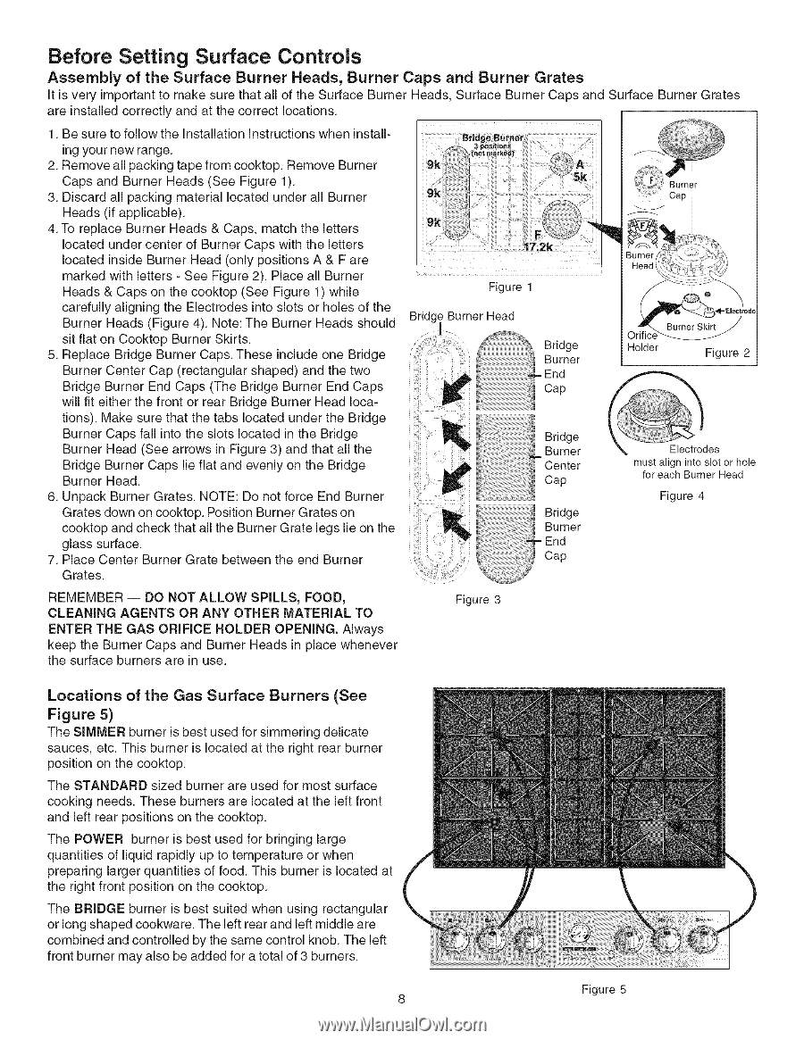
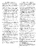
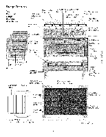
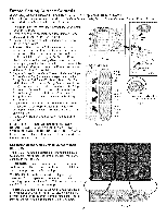
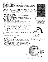
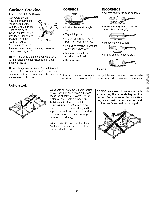
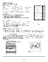
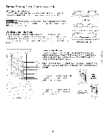
Before Setting Surface Controls Assembly of the Surface Burner Heads, Burner Caps and Burner Grates It is very important to make sure that all of the Surface Burner Heads, Surface Burner Caps and Surface Burner Grates are installed correctly and at the correct locations. 1. Be sure to follow the installation instructions when install- ing your new range. 2. Remove all packing tape from cooktop. Remove Burner Caps and Burner Heads (See Figure 1). 3. Discard all packing material located under all Burner Heads (if applicable). 4. To replace Burner Heads & Caps, match the letters located under center of Burner Caps with the letters located inside Burner Head (only positions A & F are marked with letters - See Figure 2). Place all Burner Heads & Caps on the cooktop (See Figure 1) while carefully aligning the Electrodes into slots or holes of the Burner Heads (Figure 4). Note: The Burner Heads should sit flat on Cooktop Burner Skirts. 5. Replace Bridge Burner Caps. These include one Bridge Burner Center Cap (rectangular shaped) and the two Bridge Burner End Caps (The Bridge Burner End Caps will fit either the front or rear Bridge Burner Head locations). Make sure that the tabs located under the Bridge Burner Caps fall into the slots located in the Bridge Burner Head (See arrows in Figure 3) and that all the Bridge Burner Caps lie flat and evenly on the Bridge Burner Head. 6. Unpack Burner Grates. NOTE: Do not force End Burner Grates down on cooktop. Position Burner Grates on cooktop and check that all the Burner Grate legs lie on the glass surface. 7. Place Center Burner Grate between the end Burner Grates. Burner Cap Iii Figure 1 Bridge Burner Head Bridge Burner = End Cap Holder Figure 2 _i!i!i!i!_i!i!!ii!!i!!!!!!!!!!i!!_!_! Bridge Burner - Center Cap must align into slot or hole for each Burner Head Figure 4 !!iiiii i!i¸_ REMEMBER -- DO NOT ALLOW SPILLS, FOOD, CLEANING AGENTS OR ANY OTHER MATERIAL TO ENTER THE GAS ORiFiCE HOLDER OPENING. Always keep the Burner Caps and Burner Heads in place whenever the surface burners are in use. Figure 3 Locations of the Gas Surface Burners (See Figure 5) The SIMMER burner is best used for simmering delicate sauces, etc. This burner is located at the right rear burner position on the cooktop. The STANDARD sized burner are used for most surface cooking needs. These burners are located at the left front and left rear positions on the cooktop. The POWER burner is best used for bringing large quantities of liquid rapidly up to temperature or when preparing larger quantities of food. This burner is located at the right front position on the cooktop. The BRIDGE burner is best suited when using rectangular or long shaped cookware. The left rear and left middle are combined and controlled by the same control knob. The left front burner may also be added for a total of 3 burners. 8 Figure 5
-
 1
1 -
2
-
 3
3 -
 4
4 -
 5
5 -
 6
6 -
 7
7 -
 8
8 -
 9
9 -
 10
10 -
 11
11 -
 12
12 -
 13
13 -
14
-
15
-
16
-
17
-
18
-
19
-
20
-
21
-
22
-
23
-
24
-
25
-
26
-
27
-
28
-
29
-
30
 |
 |