Kenwood 6020 Instruction Manual - Page 38
Connecting Wires to Terminals, Ground wire Black
 |
View all Kenwood 6020 manuals
Add to My Manuals
Save this manual to your list of manuals |
Page 38 highlights
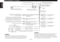
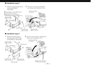
English Connecting Wires to Terminals Front left output (White) Front right output (Red) KENWOOD disc changer control input NOTE To connect the Disc changer, consult your Disc changer manual. Rear right output (Red)/ Non-fading right output (Red) Rear left output (White)/ Non-fading left output (White) FM/AM antenna input 10 Fuse (10A) Wiring harness (Accessory#) - - - - - When using the optional power amplifier, connect to its power control terminal. Depending on what antenna you are using, connect either to the control terminal of the motor antenna, or to the power terminal for the booster amplifier of the film-type antenna. P.CONT Power control wire (Blue/White) ANT CONT Motor antenna control wire (Blue) White/Black FRONT•L + White Gray/Black FRONT•R + Gray To front left speaker To front right speaker To "EXT.AMP.CONT." terminal of the amplifier having the external amp control function. To car light control switch Ignition key switch EXT. CONT. External amplifier control wire (Pink / Black) ILLUMI Automatic illumination/Dimmer control wire (Orange) Car fuse box (Main fuse) ACC Car fuse box Ignition wire (Red) Battery wire (Yellow) Battery + Ground wire (Black) - (To car chassis) Green/Black REAR•L + Green Purple/Black REAR•R + Purple To rear left speaker To rear right speaker 2WARNING If you connect the ignition wire (red) and the battery wire (yellow) to the car chassis (ground), you may cause a short circuit, that in turn may start a fire. Always connect those wires to the power source running through the fuse box. - 38 - 2CAUTION When only two speakers are being connected to the system, connect the connectors either to both the front output terminals or to both the rear output terminals (do not mix front and rear). For example, if you connect the + connector of the left speaker to a front output terminal, do not connect the - connector to a rear output terminal.
-
 1
1 -
2
-
3
-
4
-
5
-
6
-
7
-
8
-
9
-
10
-
11
-
12
-
13
-
14
-
15
-
16
-
17
-
18
-
19
-
20
-
21
-
22
-
23
-
24
-
25
-
26
-
27
-
28
-
29
-
30
-
31
-
32
-
 33
33 -
 34
34 -
 35
35 -
 36
36 -
 37
37 -
 38
38 -
 39
39 -
 40
40 -
 41
41 -
 42
42 -
 43
43 -
44
-
45
-
46
 |
 |
