Kenwood DNN992 Quick Start Guide 1 - Page 20
Bluetooth antenna area, WI-FI receiver, Supplied accessories
 |
View all Kenwood DNN992 manuals
Add to My Manuals
Save this manual to your list of manuals |
Page 20 highlights
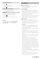
• Insulate unconnected wires with vinyl tape or other similar material. To prevent a short circuit, do not remove the caps on the ends of the unconnected wires or the terminals. • Connect the speaker wires correctly to the terminals to which they correspond. The unit may be damaged or fail to work if you share the ¤ wires or ground them to any metal part in the car. • When only two speakers are being connected to the system, connect the connectors either to both the front output terminals or to both the rear output terminals (do not mix front and rear). For example, if you connect the ¢ connector of the left speaker to a front output terminal, do not connect the ¤ connector to a rear output terminal. • After the unit is installed, check whether the brake lamps, blinkers, wipers, etc. on the car are working properly. • Mount the unit so that the mounting angle is 30° or less. • This unit has the cooling fan (P.24) to decrease the internal temperature. Do not mount the unit in a place where the cooling fan of the unit is blocked. Blocking these openings will inhibit the cooling of the internal temperature and result in malfunction. • Do not press hard on the panel surface when installing the unit to the vehicle. Otherwise scars, damage, or failure may result. • Reception may drop if there are metal objects near the Bluetooth antenna and WI-FI receiver. Bluetooth antenna area ÑÑSupplied accessories First of all, make sure that all accessories are supplied with the unit. 1 ...1 8 ...1 2 ...1 9 ...1 3 ...2 (2 m) 0...1 (3.5 m) 4 *1 ...1 5 *1 ...1 - ...1 (3 m) = *1 ...1 N/OUT GPS M4 x 8mmMAX iPod/ AV-IN2 iDalalink I/F WiFi Recever 5V=500mA SW FRONT REAR FUSE 10A WI-FI receiver PTT EXT POWER I/F HOME 6 R L • Install the WI-FI receiver besides the place enclosed by the metal. 6 ...6 (3 m) ~ ...1 7 ...6 (M5x6mm) *1 DNN992 only 20 ñ English (M5x7mm)
-
 1
1 -
2
-
3
-
4
-
5
-
6
-
7
-
8
-
9
-
10
-
11
-
12
-
13
-
14
-
 15
15 -
 16
16 -
 17
17 -
 18
18 -
 19
19 -
 20
20 -
 21
21 -
 22
22 -
 23
23 -
 24
24 -
 25
25 -
26
-
27
-
28
-
29
-
30
-
31
-
32
-
33
-
34
-
35
-
36
-
37
-
38
-
39
-
40
-
41
-
42
-
43
-
44
-
45
-
46
-
47
-
48
-
49
-
50
-
51
-
52
-
53
-
54
-
55
-
56
-
57
-
58
-
59
-
60
-
61
-
62
-
63
-
64
-
65
-
66
-
67
-
68
 |
 |
