Kenwood KDC-X395 Instruction Manual - Page 30
Installation/connection - harness
 |
UPC - 019048193025
View all Kenwood KDC-X395 manuals
Add to My Manuals
Save this manual to your list of manuals |
Page 30 highlights
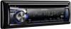
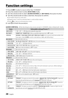
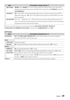
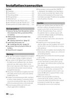
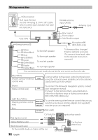
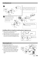
Installation/connection Part list: A Faceplate 1) B Escutcheon 1) C Mounting sleeve 1) D Wiring harness 1) E Removal tool 2) F Flat head screw (for Nissan cars 4) G Round head screw (for Toyota cars 4) H Microphone (3 m) (KDC-X695 only 1) Basic procedure 1 Remove the key from the ignition switch, then disconnect the · terminal of the car battery. 2 Make proper input and output wire connections. \ (page 32) 3 Install the unit to your car. \ (page 33) 4 Reconnect the · terminal of the car battery. 5 Reset the unit. (page 4) Warning ■ The unit can only be installed in a car with a 12 V DC power supply, negative ground. ■ If you connect the ignition wire (red) and the battery wire (yellow) to the car chassis (ground), you may cause a short circuit, that in turn may start a fire. Always connect those wires to the power source running through the fuse box. ■ Disconnect the battery's negative terminal and make all electrical connections before installing the unit. ■ Insulate unconnected wires with vinyl tape or other similar material. To prevent a short circuit, do not remove the caps on the ends of the unconnected wires or the terminals. ■ Be sure to ground this unit to the car's chassis again after installation. ■ If the power is not turned ON ("PROTECT" is displayed), the speaker wire may have a short-circuit or touched the chassis of the vehicle and the protection function may have been activated. Therefore, the speaker wire should be checked. Caution ■ If your car's ignition does not have an ACC position, connect the ignition wires to a power source that can be turned on and off with the ignition key. If you connect the ignition wire to a power source with a constant voltage supply, as with battery wires, the battery may die. ■ Do not use your own screws. Use only the screws provided. ■ Install this unit in the console of your vehicle. Make sure the faceplate will not hit the lid of the console (if any) when closing and opening. ■ After the unit is installed, check whether the brake lamps, blinkers, wipers, etc. on the car are working properly. ■ Mount the unit so that the mounting angle is 30° or less. ■ If the fuse blows, first make sure the wires are not touching to cause a short circuit, then replace the old fuse with one that has the same rating. ■ Connect the speaker wires correctly to the terminals to which they correspond. The unit may be damaged or fail to work if you share the · wires or ground them to any metal part in the car. ■ When only two speakers are being connected to the system, connect the connectors either to both the front output terminals or to both the rear output terminals (do not mix front and rear). 30 English
-
 1
1 -
2
-
3
-
4
-
5
-
6
-
7
-
8
-
9
-
10
-
11
-
12
-
13
-
14
-
15
-
16
-
17
-
18
-
19
-
20
-
21
-
22
-
23
-
24
-
 25
25 -
 26
26 -
 27
27 -
 28
28 -
 29
29 -
 30
30 -
 31
31 -
 32
32 -
 33
33 -
 34
34 -
 35
35 -
36
-
37
-
38
-
39
-
40
-
41
-
42
-
43
-
44
-
45
-
46
-
47
-
48
-
49
-
50
-
51
-
52
-
53
-
54
-
55
-
56
-
57
-
58
-
59
-
60
-
61
-
62
-
63
-
64
-
65
-
66
-
67
-
68
-
69
-
70
-
71
-
72
-
73
-
74
-
75
-
76
-
77
-
78
-
79
-
80
-
81
-
82
-
83
-
84
-
85
-
86
-
87
-
88
-
89
-
90
-
91
-
92
-
93
-
94
-
95
-
96
-
97
-
98
-
99
-
100
-
101
-
102
-
103
-
104
-
105
-
106
-
107
-
108
-
109
-
110
-
111
-
112
 |
 |