Kenwood KDC-X879 Instruction Manual - Page 57
Installation, non-Japanese cars - support
 |
View all Kenwood KDC-X879 manuals
Add to My Manuals
Save this manual to your list of manuals |
Page 57 highlights
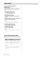
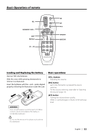
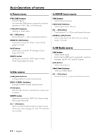
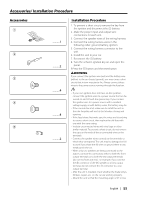
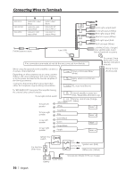
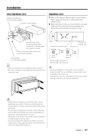
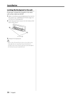
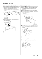
Installation non-Japanese cars Metal mounting strap (commercially available) Firewall or metal support Japanese cars 1 Refer to the section 'Removing the hard rubber frame' (page 59) and then remove the hard rubber frame. 2 Align the holes in the unit (two locations on each side) with the vehicle mounting bracket and secure the unit with the accessory screws. Bend the tabs of the mounting sleeve with a screwdriver or similar utensil and attach it in place. Phillips truss head sheet metal screw (commercially available) Screw (M4X8) (commercially available) T N NT T/N T: Toyota cars N: Nissan cars 3 ø5mm 8 mm MAX. 4 ø5mm Accessory3...for Nissan car Accessory4 ...for Toyota car 8mm MAX. • Make sure that the unit is installed securely in place. If the unit is unstable, it may malfunction (for example, the sound may skip). • During installation, do not use any screws except for those provided. The use of different screws might result in damage to the main unit. • Damage may occur if a screwdriver or similar tool is used with excessive force during the installations. • To attach this unit, make sure the front of the control panel faces you and fit it into the mounting sleeve by pressing the four corners of the hard rubber frame at the same time. Do not apply strong pressure to other sections than the corners; otherwise troubles such as the impossibility of opening or closing the panel may result. • The hollow at the center of the rubber frame is designed to make it easier to remove discs. If you do not want the hollow to be visible, mount the rubber frame in the opposite direction (with the flat side at the top instead of the bottom). English | 57
-
 1
1 -
2
-
3
-
4
-
5
-
6
-
7
-
8
-
9
-
10
-
11
-
12
-
13
-
14
-
15
-
16
-
17
-
18
-
19
-
20
-
21
-
22
-
23
-
24
-
25
-
26
-
27
-
28
-
29
-
30
-
31
-
32
-
33
-
34
-
35
-
36
-
37
-
38
-
39
-
40
-
41
-
42
-
43
-
44
-
45
-
46
-
47
-
48
-
49
-
50
-
51
-
 52
52 -
 53
53 -
 54
54 -
 55
55 -
 56
56 -
 57
57 -
 58
58 -
 59
59 -
 60
60 -
 61
61 -
 62
62 -
63
-
64
 |
 |
