LG 32LX2D Service Manual - Page 11
Adjustment Instruction - lcd tv
 |
View all LG 32LX2D manuals
Add to My Manuals
Save this manual to your list of manuals |
Page 11 highlights
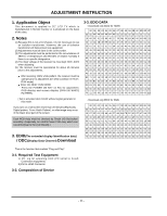
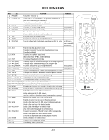
ADJUSTMENT INSTRUCTION 1. Application Object This document is applied to 32" LCD TV which is manufactured in Monitor Factory or is produced on the basis of this data. 2. Notes (1) Because this is not a hot chassis, it is not necessary to use an isolation transformer. However, the use of isolation transformer will help protect test equipment. (2) Adjustments must be done in the correct order. (3) The adjustments must be performed in the circumstance of 25±5°C of temperature and 65±10% of relative humidity if there is no specific designation. (4) The input voltage of the receiver be must kept 220V, 60Hz when adjusting. (5) The receiver must be operational for about 15 minutes prior to the adjustments. After receiving 100% white pattern, the receiver must be operate prior to adjustment.(Or white condition in HEATRUN mode) Enter into HEAT-RUN MODE - Press the POWER ON KEY on R/C for adjustment. OSD display and screen display 100% full WHITE PATTERN. [ Set is activated HEAT-RUN without signal generator in this mode. If you turn on a still screen more than 20 minutes (Especially Digital pattern, Cross Hatch Pattern), an afterimage may occur in the black level part of the screen. Each PCB Assy must be checked by Check JIG Set before assembly. (Especially, be careful Power PCB Assy which can cause Damage to the LCD Module.) 3. EDID(The extended display Identification data) / DDC(Display Data Channel) Download 3-3. EDID DATA - Download only EDID for HDMI. 00 01 02 03 04 05 06 07 08 09 0A 0B 0C 0D 0E 0F 00 00 FF FF FF FF FF FF 00 1E 6D 00 00 01 01 01 01 10 00 0F 01 03 80 46 27 78 0A 36 E9 A3 56 49 9B 25 20 11 48 4B 4F EE 80 31 4F 45 4F 61 4F 01 01 01 01 30 01 01 01 01 01 01 64 19 00 40 41 00 26 30 18 88 40 36 00 BA 88 21 00 00 18 00 00 00 FD 00 38 4B 1E 50 3D 08 00 0A 20 20 20 20 20 20 00 00 00 FC 00 33 60 32 4C 58 32 44 2D 41 41 20 20 20 20 00 00 00 00 70 00 00 00 00 00 00 00 00 00 00 00 00 00 00 01 48 80 02 03 1A 72 23 15 07 50 47 85 01 04 14 13 12 00 90 83 0F 00 00 65 03 0C 00 10 00 01 1D 80 D0 72 1C A0 16 20 10 2C 25 80 C4 8E 21 00 00 9E 01 1D 80 18 B0 71 1C 16 20 58 2C 25 00 C4 8E 21 00 00 9E 01 1D C0 00 BC 52 D0 1E 20 B8 28 55 40 C4 8E 21 00 00 1E D0 01 1D 00 72 51 D0 1E 20 6E 28 55 00 C4 8E 21 00 E0 00 1E 8C 0A D0 90 20 40 31 20 0C 40 55 00 C4 8E F0 21 00 00 18 00 00 00 00 00 00 00 00 00 00 00 EB - Download only EDID for RGB. 00 01 02 03 04 05 06 07 08 09 0A 0B 0C 0D 0E 0F 00 00 FF FF FF FF FF FF 00 1E 6D 5D 46 01 01 01 01 10 07 0F 01 03 68 46 27 96 0A FB 2C A3 57 47 9A 25 20 10 48 4B AF CE 00 31 4F 45 4F 61 4F 01 01 01 01 30 01 01 01 01 01 01 64 19 00 40 41 00 26 30 18 88 40 36 00 BC 88 21 00 00 18 00 00 00 FD 00 38 4B 1F 50 3D 08 00 0A 20 20 20 20 20 20 00 00 00 FC 00 33 60 32 4C 58 32 44 2D 41 41 0A 20 20 20 00 00 00 00 70 00 00 00 00 00 00 00 00 00 00 00 00 00 00 00 48 This is the function that enables "Plug and Play". 3-1. Required Test Equipment 1) PC, Jig for adjusting DDC (PC serial to D-sub. Connection equipment) 2) DVI to HDMI Connector 3-2. Composition of Device - 11 -
-
 1
1 -
2
-
3
-
4
-
5
-
 6
6 -
 7
7 -
 8
8 -
 9
9 -
 10
10 -
 11
11 -
 12
12 -
 13
13 -
 14
14 -
 15
15 -
 16
16 -
17
-
18
-
19
-
20
-
21
-
22
-
23
-
24
-
25
-
26
-
27
-
28
-
29
-
30
-
31
-
32
-
33
-
34
-
35
-
36
-
37
-
38
-
39
-
40
-
41
-
42
-
43
-
44
-
45
-
46
-
47
-
48
-
49
-
50
-
51
-
52
-
53
-
54
-
55
-
56
-
57
-
58
-
59
-
60
-
61
-
62
-
63
-
64
-
65
-
66
-
67
-
68
-
69
-
70
-
71
-
72
 |
 |