LG LAN121CNM Service Manual - Page 40
To remove the Control Box., To remove the Discharge Grille., To remove the Evaporator.
 |
View all LG LAN121CNM manuals
Add to My Manuals
Save this manual to your list of manuals |
Page 40 highlights
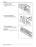
Disassembly 2. To remove the Control Box. • Remove securing screws. • Pull the control box out from the chassis carefully. 3. To remove the Discharge Grille. • Unhook the discharge grille and pull the discharge grille out from the chassis carefully. Screw 4. To remove the Evaporator. • Remove 3 screws securing the evaporator(at the left 2EA in the Eva Holder, at the right 1EA). • When repair, do not damage the Caution label. 40 Room Air Conditioner
-
 1
1 -
2
-
3
-
4
-
5
-
6
-
7
-
8
-
9
-
10
-
11
-
12
-
13
-
14
-
15
-
16
-
17
-
18
-
19
-
20
-
21
-
22
-
23
-
24
-
25
-
26
-
27
-
28
-
29
-
30
-
31
-
32
-
33
-
34
-
 35
35 -
 36
36 -
 37
37 -
 38
38 -
 39
39 -
 40
40 -
 41
41 -
 42
42 -
 43
43 -
 44
44 -
 45
45 -
46
-
47
-
48
-
49
-
50
-
51
-
52
-
53
-
54
-
55
-
56
-
57
-
58
-
59
-
60
-
61
-
62
-
63
-
64
-
65
-
66
-
67
-
68
-
69
-
70
-
71
 |
 |

40
Room Air Conditioner
Disassembly
2. To remove the Control Box.
•
Remove securing screws.
•
Pull the control box out from the chassis
carefully.
3. To remove the Discharge Grille.
•
Unhook the discharge grille and pull the
discharge grille out from the chassis carefully.
4. To remove the Evaporator.
•
Remove 3 screws securing the evaporator(at the
left 2EA in the Eva Holder, at the right 1EA).
Screw
•
When repair, do not damage the Caution label.