LG RU-27FB30C Operation Guide - Page 13
Hook Up Cable Service CATV and VCR
 |
View all LG RU-27FB30C manuals
Add to My Manuals
Save this manual to your list of manuals |
Page 13 highlights
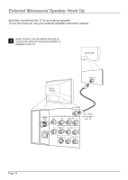
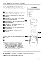
Hook Up Cable Service (CATV) and VCR Connect a VCR and Cable service to the TV. Cable TV Wall Jack 1 Locate the Antenna/Cable (In) jack on the back of the VCR. Connect the CATV cable that runs 2 from the wall directly to this jack, according to one of the connection diagrams shown at right. Remove the back of the remote 3 and install two AA batteries. In Cable Box Out output switch 3 4 RF Coaxial Wire (75 ohm) Typical TV Back VCR Back In output switch 3 4 Out Video Audio Back of the Remote Plug in the TV. The TV is designed 4 to operate on standard current, 120-volt 60 Hertz AC. Do not attempt to operate it on DC Current. Matrix Out Antenna Cable Component Video Input Pr Pb R Audio L Y Video In R Audio In L M.P.I. S-Video In R Audio In L A/V cables Not inlcuded with the TV 120 Volt 60 Hz AC Tune the VCR and television to channel 3 or 4 and use the cable box to change channels. No A/V cables are included with your TV. Without A/V cables, most VCRs will not play videocassettes in stereo sound. Cable TV Wall Jack RF Coaxial Wire (75 ohm) Typical TV Back VCR Back In output switch 3 4 Out Video Audio Antenna Cable Matrix Out Component Video Input Pr Pb R Audio L Y Video In R Audio In L M.P.I. S-Video In R Audio In L Page 13
-
 1
1 -
2
-
3
-
4
-
5
-
6
-
7
-
 8
8 -
 9
9 -
 10
10 -
 11
11 -
 12
12 -
 13
13 -
 14
14 -
 15
15 -
 16
16 -
 17
17 -
 18
18 -
19
-
20
-
21
-
22
-
23
-
24
-
25
-
26
-
27
-
28
-
29
-
30
-
31
-
32
-
33
-
34
-
35
-
36
-
37
-
38
-
39
-
40
-
41
-
42
-
43
-
44
-
45
-
46
-
47
-
48
-
49
-
50
-
51
-
52
-
53
-
54
-
55
-
56
 |
 |
