LG RU-42PZ90 Owners Manual - Page 8
Connection Options
 |
UPC - 719192166066
View all LG RU-42PZ90 manuals
Add to My Manuals
Save this manual to your list of manuals |
Page 8 highlights
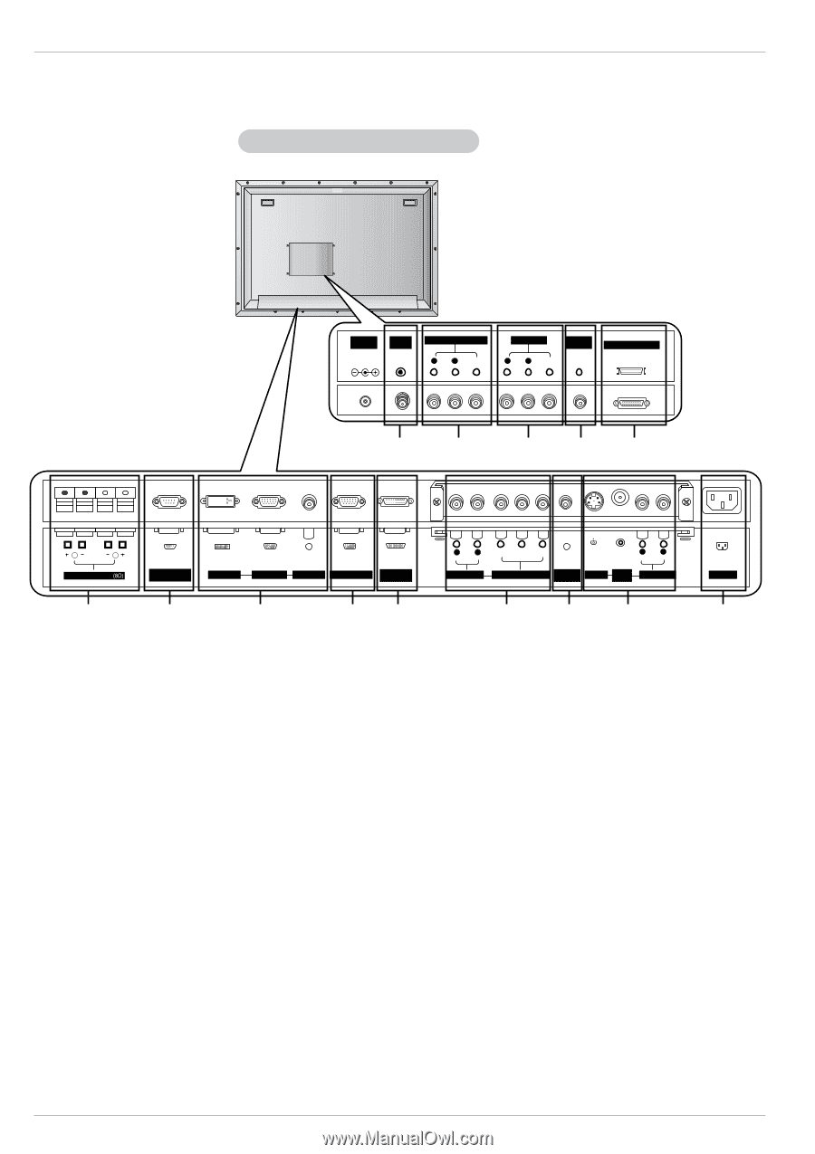
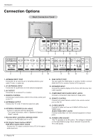
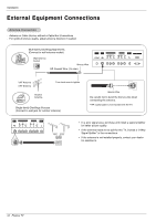
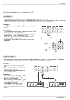
Introduction Connection Options Back Connection Panel DC IN (DC 12V) ANT IN +75 Ω AV(EXPANDED) INPUT R AUDIO L (MONO) VIDEO AV OUTPUT REMOTE CONTROL R AUDIO L VIDEO EXPANDED OUTPUT 1 2 3 4 5 ( )R( ) ( )L ( ) EXTERNAL SPEAKER RS-232C INPUT (CONTROL/SERVICE) DVI INPUT RGB INPUT AUDIO INPUT RGB OUTPUT EXPANDED INPUT 6 7 8 9 10 R AUDIO L Y PB PR R AUDIO L (MONO) AUDIO INPUT COMPONENT INPUT REMOTE CONTROL S-VIDEO VIDEO INPUT AUDIO INPUT 11 12 13 AC INPUT 14 1. ANTENNA INPUT PORT Connection for an over-the-air or terrestrial antenna, your cable TV wire, or cable box. 2. AV (EXPANDED) INPUT Connection for audio/video out from external equipment. 3. AV OUTPUT Connection for a second TV or monitor. 4. REMOTE CONTROL Connect your wired remote control to the remote control port on the TV. 5. EXPANDED OUTPUT Connect the TV to the TV with the tuner box cable. 6. EXTERNAL SPEAKER (8 ohm output) Connect to optional external speaker(s). * For further information, refer to 'Speaker & Speaker Stand' manual. 7. RS-232C INPUT (CONTROL/SERVICE) PORT Connect to the RS-232C port on a PC. 8. DVI (Digital Visual Interface) INPUT/ RGB INPUT/AUDIO INPUT JACKS Connect the TV output connector from a PC to the appropriate input port. 9. RGB OUTPUT PORT You can watch the RGB signal on another monitor, connect RGB OUTPUT to another monitor's PC input port. 10. EXPANDED INPUT Connect the plasma display to the Tuner with the tuner box cable supplied. 11. COMPONENT INPUT/AUDIO INPUT JACKS Connect a component video device to these jacks. 12. REMOTE CONTROL Connect your wired remote control to the remote control port on the TV. 13. S-VIDEO INPUTS Connect S-Video out from an S-VIDEO VCR to the SVIDEO input. AUDIO/VIDEO INPUT JACKS Connect audio/video out from external equipment to these jacks. 14. POWER CORD SOCKET This TV operates on an AC power. The voltage is indicated on the Specifications page. Never attempt to operate the TV on DC power. 8 Plasma TV
-
 1
1 -
2
-
 3
3 -
 4
4 -
 5
5 -
 6
6 -
 7
7 -
 8
8 -
 9
9 -
 10
10 -
 11
11 -
 12
12 -
 13
13 -
14
-
15
-
16
-
17
-
18
-
19
-
20
-
21
-
22
-
23
-
24
-
25
-
26
-
27
-
28
-
29
-
30
-
31
-
32
-
33
-
34
-
35
-
36
-
37
-
38
-
39
-
40
-
41
-
42
-
43
-
44
-
45
-
46
-
47
-
48
 |
 |