Lantronix UDS1100 UDS1100 - User Guide - Page 7

List of s, List of Tables, B-5. Wiring Diagram for Lantronix Modem Cable - manual

Page 7 highlights

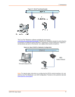
List of Figures Figure 2-1. Serial Tunneling Example 11 Figure 2-2. Direct TCP/IP or Redirector Configuration 11 Figure 2-3. Product Label 13 Figure 2-4. Sample Hardware Address 13 Figure 3-1. UDS1100-POE Version Connected to Serial Device and Network ______ 14 Figure 3-2. Standard UDS1100 Connected to Serial Device and Network _________ 15 Figure 5-1. Web-Manager Login Window 22 Figure 5-2. Lantronix Web-Manager 23 Figure 5-3. Network Settings 24 Figure 5-4. Server Settings 26 Figure 5-5. Hostlist Settings 28 Figure 5-6. Channel Serial Settings 29 Figure 5-7. TCP Connection Settings 31 Figure 5-8. UDP Connection Settings 34 Figure 5-9. Apply Settings and Apply Defaults 35 Figure 6-1. MAC Address 37 Figure 6-2. Setup Menu Options 37 Figure 7-1. Network Settings 38 Figure 8-1. Serial Port Settings 41 Figure 8-2. Interface Mode 42 Figure 8-3. Hostlist Option 46 Figure 9-1. Expert Settings 55 Figure 9-2. Security Settings 57 Figure 10-1. TFTP Window 62 Figure B-1. Serial Interface 71 Figure B-2. DB25 Female DCE Interface RS232 71 Figure B-3. DB25 Female Interface RS422 (4 wire mode 72 Figure B-4. DB25 Female Interface RS485 (2 wire mode 72 Figure B-5. Wiring Diagram for Lantronix Modem Cable, Part No. 500-163 ________ 73 List of Tables Table 7-1. BootP/DHCP/AutoIP options 38 Table 7-2. Standard IP Network Netmasks 39 Table 8-1. Interface Mode Options 42 Table 8-2. Common Interface Mode Settings 42 Table 8-3. Flow Control Options 43 Table 8-4. Reserved Port Numbers 43 Table 8-5. Connect Mode Options 44 Table 8-6. Manual Connection Address Example 46 Table 8-7. Modem Mode Messages 48 Table 8-8. Modem Mode Commands 49 Table 8-9. Disconnect Mode Options 51 Table 8-10. Flush Mode Options 52 Table 8-11. Pack Control Options 52 Table 10-1. Firmware Files 61 Table 11-1. Monitor Mode Commands 65 Table 11-2. Command Response Codes 66 Table A-1. UDS1100 LEDs 67 Table A-2. Problems and Error Messages 68 Table C-1. UDS1100 Technical Specifications 75 UDS1100 User Guide 7

  • 1
  • 2
  • 3
  • 4
  • 5
  • 6
  • 7
  • 8
  • 9
  • 10
  • 11
  • 12
  • 13
  • 14
  • 15
  • 16
  • 17
  • 18
  • 19
  • 20
  • 21
  • 22
  • 23
  • 24
  • 25
  • 26
  • 27
  • 28
  • 29
  • 30
  • 31
  • 32
  • 33
  • 34
  • 35
  • 36
  • 37
  • 38
  • 39
  • 40
  • 41
  • 42
  • 43
  • 44
  • 45
  • 46
  • 47
  • 48
  • 49
  • 50
  • 51
  • 52
  • 53
  • 54
  • 55
  • 56
  • 57
  • 58
  • 59
  • 60
  • 61
  • 62
  • 63
  • 64
  • 65
  • 66
  • 67
  • 68
  • 69
  • 70
  • 71
  • 72
  • 73
  • 74
  • 75
  • 76
  • 77
  • 78
  • 79
  • 80
  • 81
  • 82
  • 83
  • 84
  • 85

UDS1100 User Guide
7
List of Figures
Figure 2-1. Serial Tunneling Example
______________________________________ 11
Figure 2-2. Direct TCP/IP or Redirector Configuration
_________________________ 11
Figure 2-3. Product Label
_______________________________________________ 13
Figure 2-4. Sample Hardware Address
_____________________________________ 13
Figure 3-1. UDS1100-POE Version Connected to Serial Device and Network
______ 14
Figure 3-2. Standard UDS1100 Connected to Serial Device and Network
_________ 15
Figure 5-1. Web-Manager Login Window
___________________________________ 22
Figure 5-2. Lantronix Web-Manager
_______________________________________ 23
Figure 5-3. Network Settings
____________________________________________ 24
Figure 5-4. Server Settings
______________________________________________ 26
Figure 5-5. Hostlist Settings
_____________________________________________ 28
Figure 5-6. Channel Serial Settings
_______________________________________ 29
Figure 5-7. TCP Connection Settings
______________________________________ 31
Figure 5-8. UDP Connection Settings
______________________________________ 34
Figure 5-9. Apply Settings and Apply Defaults
_______________________________ 35
Figure 6-1. MAC Address
_______________________________________________ 37
Figure 6-2. Setup Menu Options
__________________________________________ 37
Figure 7-1. Network Settings
____________________________________________ 38
Figure 8-1. Serial Port Settings
___________________________________________ 41
Figure 8-2. Interface Mode
______________________________________________ 42
Figure 8-3. Hostlist Option
______________________________________________ 46
Figure 9-1. Expert Settings
______________________________________________ 55
Figure 9-2. Security Settings
_____________________________________________ 57
Figure 10-1. TFTP Window
______________________________________________ 62
Figure B-1. Serial Interface
______________________________________________ 71
Figure B-2. DB25 Female DCE Interface RS232
_____________________________ 71
Figure B-3. DB25 Female Interface RS422 (4 wire mode)
______________________ 72
Figure B-4. DB25 Female Interface RS485 (2 wire mode)
______________________ 72
Figure B-5. Wiring Diagram for Lantronix Modem Cable, Part No. 500-163
________ 73
List of Tables
Table 7-1. BootP/DHCP/AutoIP options
____________________________________ 38
Table 7-2. Standard IP Network Netmasks
_________________________________ 39
Table 8-1. Interface Mode Options
________________________________________ 42
Table 8-2. Common Interface Mode Settings
________________________________ 42
Table 8-3. Flow Control Options
__________________________________________ 43
Table 8-4. Reserved Port Numbers
_______________________________________ 43
Table 8-5. Connect Mode Options
________________________________________ 44
Table 8-6. Manual Connection Address Example
____________________________ 46
Table 8-7. Modem Mode Messages
_______________________________________ 48
Table 8-8. Modem Mode Commands
______________________________________ 49
Table 8-9. Disconnect Mode Options
______________________________________ 51
Table 8-10. Flush Mode Options
__________________________________________ 52
Table 8-11. Pack Control Options
_________________________________________ 52
Table 10-1. Firmware Files
______________________________________________ 61
Table 11-1. Monitor Mode Commands
_____________________________________ 65
Table 11-2. Command Response Codes
___________________________________ 66
Table A-1. UDS1100 LEDs ______________________________________________ 67
Table A-2. Problems and Error Messages
__________________________________ 68
Table C-1. UDS1100 Technical Specifications
_______________________________ 75