Lenovo B590 Hardware Maintenance Manual - Page 53
Hard disk drive assembly, Removal steps of memory modules, When installing, Attention
 |
View all Lenovo B590 manuals
Add to My Manuals
Save this manual to your list of manuals |
Page 53 highlights
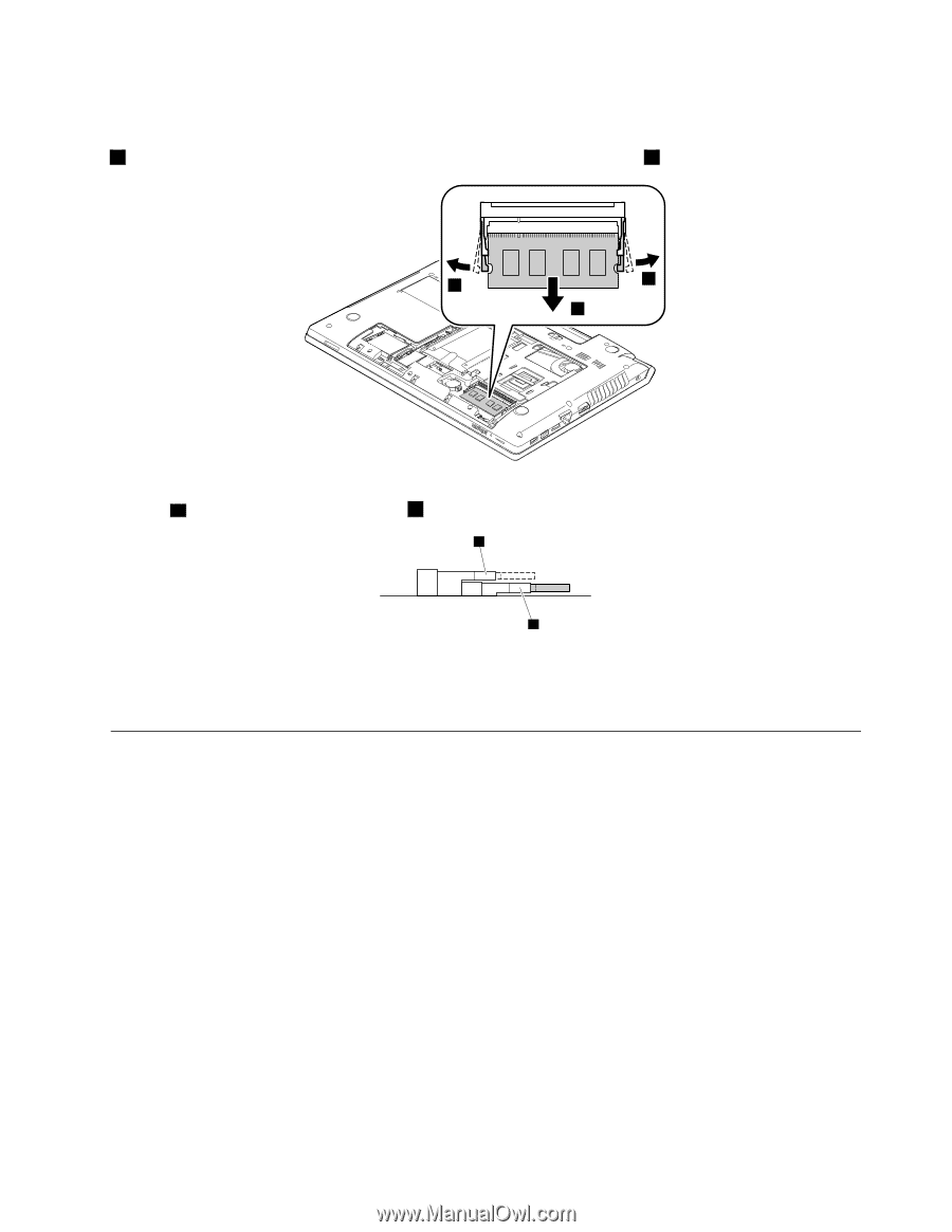
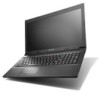
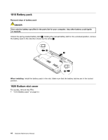
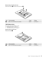
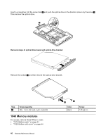
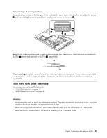
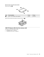
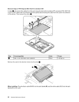
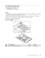
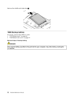
Removal steps of memory modules Release the two latches on both edges of the socket at the same time in the direction shown by the arrows 1 , and then unplug the memory module in the direction shown by the arrow 2 . 1 1 2 Note: If only one memory module is used on the computer you are servicing, the card must be installed in SLOT-0 ( a : lower slot), but not in SLOT-1 ( b : upper slot). b a When installing: Insert the notched end of the memory module into the socket. Press the memory module firmly, and pivot it until it snaps into place. Make sure that it is firmly installed in the slot and does not move easily. 1050 Hard disk drive assembly For access, remove these FRUs in order: • "1010 Battery pack" on page 44 • "1020 Bottom slot cover" on page 44 Attention: • Do not drop the drive or apply any physical shock to it. The drive is sensitive to physical shock. Improper handling can cause damage and permanent loss of data. • Before removing the drive, have the user make a backup copy of all the information on it if possible. • Never remove the drive while the computer is operating or is in suspend mode. Chapter 7. Removing and replacing a FRU 47
-
 1
1 -
2
-
3
-
4
-
5
-
6
-
7
-
8
-
9
-
10
-
11
-
12
-
13
-
14
-
15
-
16
-
17
-
18
-
19
-
20
-
21
-
22
-
23
-
24
-
25
-
26
-
27
-
28
-
29
-
30
-
31
-
32
-
33
-
34
-
35
-
36
-
37
-
38
-
39
-
40
-
41
-
42
-
43
-
44
-
45
-
46
-
47
-
 48
48 -
 49
49 -
 50
50 -
 51
51 -
 52
52 -
 53
53 -
 54
54 -
 55
55 -
 56
56 -
 57
57 -
 58
58 -
59
-
60
-
61
-
62
-
63
-
64
-
65
-
66
-
67
-
68
-
69
-
70
-
71
-
72
-
73
-
74
-
75
-
76
-
77
-
78
-
79
-
80
-
81
-
82
-
83
-
84
-
85
-
86
-
87
-
88
-
89
-
90
-
91
-
92
-
93
-
94
-
95
-
96
-
97
-
98
-
99
-
100
-
101
-
102
-
103
-
104
 |
 |