Lenovo B590 Hardware Maintenance Manual - Page 66
Microphone assembly, Removal steps of power board, Removal steps of touch pad bracket
 |
View all Lenovo B590 manuals
Add to My Manuals
Save this manual to your list of manuals |
Page 66 highlights
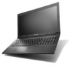
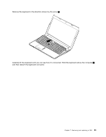
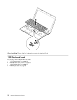
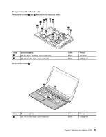
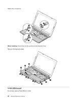
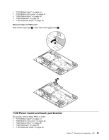
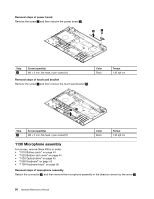
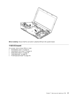
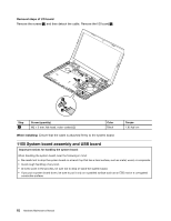
Removal steps of power board Remove the screw 1 and then remove the power board 2 . 2 1 Step 1 Screw (quantity) M2 × 3 mm, flat-head, nylon-coated (1) Removal steps of touch pad bracket Remove the screw 1 and then remove the touch pad bracket 2 . Color Black Torque 1.85 kgf-cm 2 1 Step 1 Screw (quantity) M2 × 3 mm, flat-head, nylon-coated (1) Color Black Torque 1.85 kgf-cm 1130 Microphone assembly For access, remove these FRUs in order: • "1010 Battery pack" on page 44 • "1020 Bottom slot cover" on page 44 • "1030 Optical drive" on page 45 • "1090 Keyboard" on page 53 • "1100 Keyboard bezel" on page 56 Removal steps of microphone assembly Detach the connector 1 , and then remove the microphone assembly in the direction shown by the arrow 2 . 60 Hardware Maintenance Manual
-
 1
1 -
2
-
3
-
4
-
5
-
6
-
7
-
8
-
9
-
10
-
11
-
12
-
13
-
14
-
15
-
16
-
17
-
18
-
19
-
20
-
21
-
22
-
23
-
24
-
25
-
26
-
27
-
28
-
29
-
30
-
31
-
32
-
33
-
34
-
35
-
36
-
37
-
38
-
39
-
40
-
41
-
42
-
43
-
44
-
45
-
46
-
47
-
48
-
49
-
50
-
51
-
52
-
53
-
54
-
55
-
56
-
57
-
58
-
59
-
60
-
 61
61 -
 62
62 -
 63
63 -
 64
64 -
 65
65 -
 66
66 -
 67
67 -
 68
68 -
 69
69 -
 70
70 -
 71
71 -
72
-
73
-
74
-
75
-
76
-
77
-
78
-
79
-
80
-
81
-
82
-
83
-
84
-
85
-
86
-
87
-
88
-
89
-
90
-
91
-
92
-
93
-
94
-
95
-
96
-
97
-
98
-
99
-
100
-
101
-
102
-
103
-
104
 |
 |
