Lenovo E4325 Laptop Hardware Maintenance Manual - Lenovo E4325 - Page 73
Thermal module
 |
View all Lenovo E4325 Laptop manuals
Add to My Manuals
Save this manual to your list of manuals |
Page 73 highlights
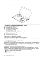
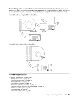
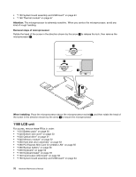
Disconnect the connector, and then remove the USB board. 1 2 3 1160 Thermal module For access, remove these FRUs in order: • "1010 Battery pack" on page 50 • "1020 Bottom slot cover" on page 50 • "1030 Optical drive" on page 51 • "1040 Memory module" on page 52 • "1050 Hard disk drive assembly" on page 53 • "1060 PCI Express Mini Card for wireless LAN" on page 55 • "1080 Backup battery" on page 56 • "1090 Keyboard" on page 56 • "1100 Keyboard bezel" on page 59 • "1150 System board assembly and USB board" on page 64 Removal steps of thermal module Detach the fan connector 1 . 1 When installing: Ensure that the connector is firmly attached. Chapter 8. Removing and replacing a FRU 67
-
 1
1 -
2
-
3
-
4
-
5
-
6
-
7
-
8
-
9
-
10
-
11
-
12
-
13
-
14
-
15
-
16
-
17
-
18
-
19
-
20
-
21
-
22
-
23
-
24
-
25
-
26
-
27
-
28
-
29
-
30
-
31
-
32
-
33
-
34
-
35
-
36
-
37
-
38
-
39
-
40
-
41
-
42
-
43
-
44
-
45
-
46
-
47
-
48
-
49
-
50
-
51
-
52
-
53
-
54
-
55
-
56
-
57
-
58
-
59
-
60
-
61
-
62
-
63
-
64
-
65
-
66
-
67
-
 68
68 -
 69
69 -
 70
70 -
 71
71 -
 72
72 -
 73
73 -
 74
74 -
 75
75 -
 76
76 -
 77
77 -
 78
78 -
79
-
80
-
81
-
82
-
83
-
84
-
85
-
86
-
87
-
88
 |
 |
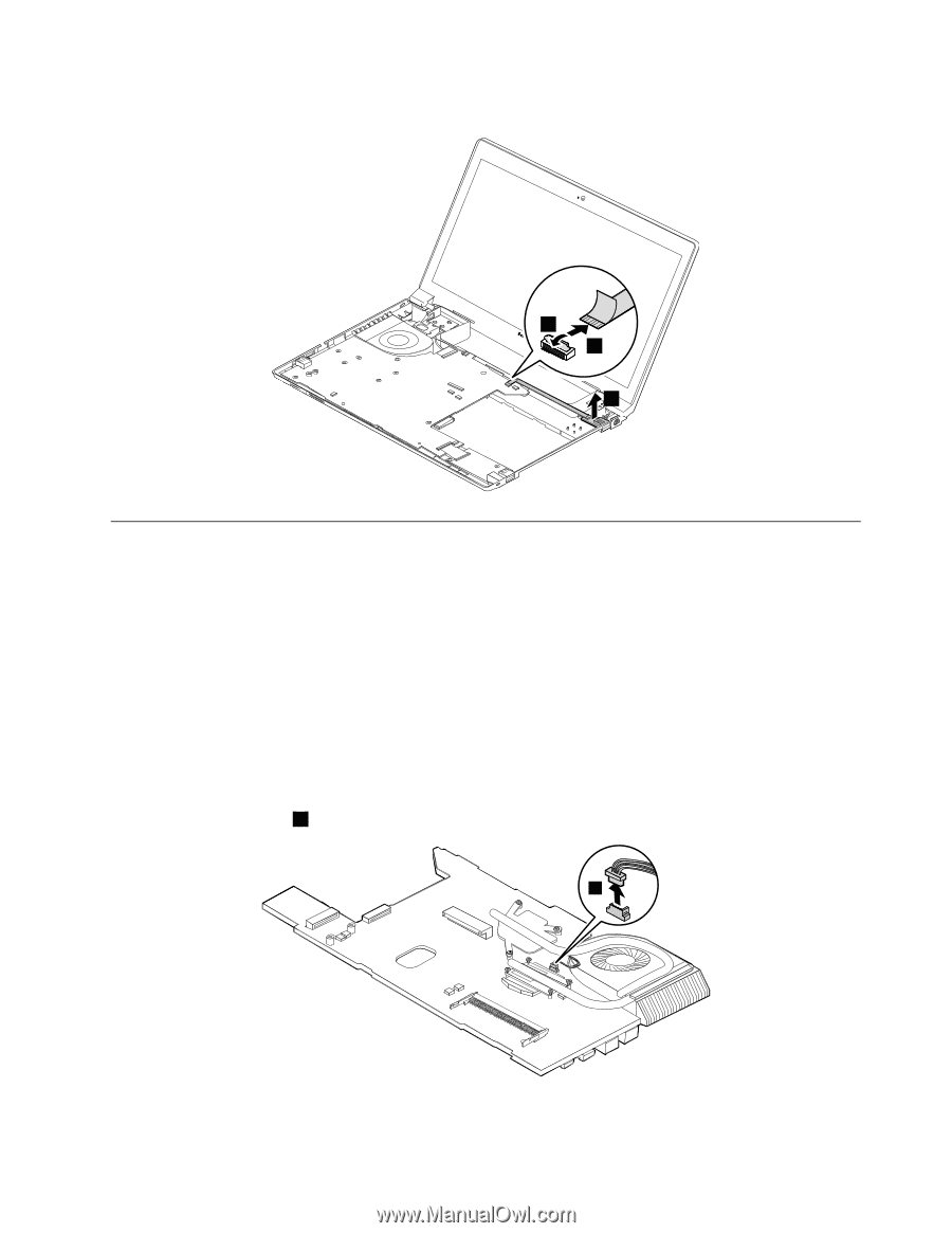
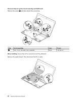
Disconnect the connector, and then remove the USB board.
1
3
2
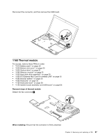
1160 Thermal module
For access, remove these FRUs in order:
•
“1010 Battery pack” on page 50
•
“1020 Bottom slot cover” on page 50
•
“1030 Optical drive” on page 51
•
“1040 Memory module” on page 52
•
“1050 Hard disk drive assembly” on page 53
•
“1060 PCI Express Mini Card for wireless LAN” on page 55
•
“1080 Backup battery” on page 56
•
“1090 Keyboard” on page 56
•
“1100 Keyboard bezel” on page 59
•
“1150 System board assembly and USB board” on page 64
Removal steps of thermal module
Detach the fan connector
1
.
1
When installing:
Ensure that the connector is firmly attached.
Chapter 8
.
Removing and replacing a FRU
67