Lenovo E4325 Laptop Hardware Maintenance Manual - Lenovo E4325 - Page 77
Removal steps of LCD unit, When installing
 |
View all Lenovo E4325 Laptop manuals
Add to My Manuals
Save this manual to your list of manuals |
Page 77 highlights
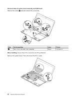
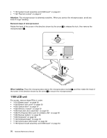
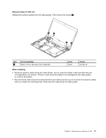
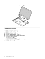
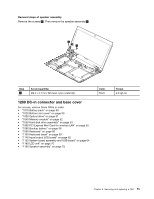
Removal steps of LCD unit Release the antenna cables from the cable guides. Then remove the screws 1 . 1 1 1 1 Step 1 Screw (quantity) M2.5 × 6 mm, flat-head, nylon-coated (4) Color Silver Torque 4.0 kgf-cm When installing: • Route the antenna cables along the cable guides. As you route the cables, make sure that they are not subjected to any tension. Tension could cause the cables to be damaged by the cable guides, or a wire to be broken. • Ensure that the LCD connector is attached firmly and make sure that you do not pinch the antenna cables when you attach the LCD assembly. Route the LCD cable along the cable guides. Chapter 8. Removing and replacing a FRU 71
-
 1
1 -
2
-
3
-
4
-
5
-
6
-
7
-
8
-
9
-
10
-
11
-
12
-
13
-
14
-
15
-
16
-
17
-
18
-
19
-
20
-
21
-
22
-
23
-
24
-
25
-
26
-
27
-
28
-
29
-
30
-
31
-
32
-
33
-
34
-
35
-
36
-
37
-
38
-
39
-
40
-
41
-
42
-
43
-
44
-
45
-
46
-
47
-
48
-
49
-
50
-
51
-
52
-
53
-
54
-
55
-
56
-
57
-
58
-
59
-
60
-
61
-
62
-
63
-
64
-
65
-
66
-
67
-
68
-
69
-
70
-
71
-
 72
72 -
 73
73 -
 74
74 -
 75
75 -
 76
76 -
 77
77 -
 78
78 -
 79
79 -
 80
80 -
 81
81 -
 82
82 -
83
-
84
-
85
-
86
-
87
-
88
 |
 |
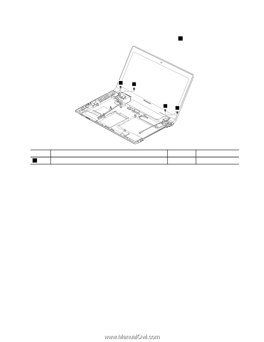
Removal steps of LCD unit
Release the antenna cables from the cable guides. Then remove the screws
1
.
1
1
1
1
Step
Screw (quantity)
Color
Torque
1
M2.5 × 6 mm, flat-head, nylon-coated (4)
Silver
4.0 kgf-cm
When installing:
•
Route the antenna cables along the cable guides. As you route the cables, make sure that they are
not subjected to any tension. Tension could cause the cables to be damaged by the cable guides,
or a wire to be broken.
•
Ensure that the LCD connector is attached firmly and make sure that you do not pinch the antenna cables
when you attach the LCD assembly. Route the LCD cable along the cable guides.
Chapter 8
.
Removing and replacing a FRU
71