Lenovo E4325 Laptop Hardware Maintenance Manual - Lenovo E4325 - Page 82
LCD panel, LCD cable, and hinges, Removal steps of camera, When installing
 |
View all Lenovo E4325 Laptop manuals
Add to My Manuals
Save this manual to your list of manuals |
Page 82 highlights
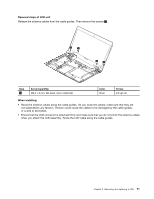
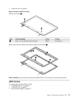
Removal steps of camera Remove the camera from the LCD cover as shown in the following illustration. Note: The camera is stuck on the top center of the LCD cover. 1 2 When installing: Stick the camera to the top center of the LCD cover and adjust the placement to make sure that the connector is attached firmly. 2030 LCD panel, LCD cable, and hinges For access, remove these FRUs in order: • "1010 Battery pack" on page 50 • "1180 LCD unit" on page 70 • "2010 LCD front bezel" on page 74 76 Hardware Maintenance Manual
-
 1
1 -
2
-
3
-
4
-
5
-
6
-
7
-
8
-
9
-
10
-
11
-
12
-
13
-
14
-
15
-
16
-
17
-
18
-
19
-
20
-
21
-
22
-
23
-
24
-
25
-
26
-
27
-
28
-
29
-
30
-
31
-
32
-
33
-
34
-
35
-
36
-
37
-
38
-
39
-
40
-
41
-
42
-
43
-
44
-
45
-
46
-
47
-
48
-
49
-
50
-
51
-
52
-
53
-
54
-
55
-
56
-
57
-
58
-
59
-
60
-
61
-
62
-
63
-
64
-
65
-
66
-
67
-
68
-
69
-
70
-
71
-
72
-
73
-
74
-
75
-
76
-
 77
77 -
 78
78 -
 79
79 -
 80
80 -
 81
81 -
 82
82 -
 83
83 -
 84
84 -
 85
85 -
 86
86 -
 87
87 -
88
 |
 |
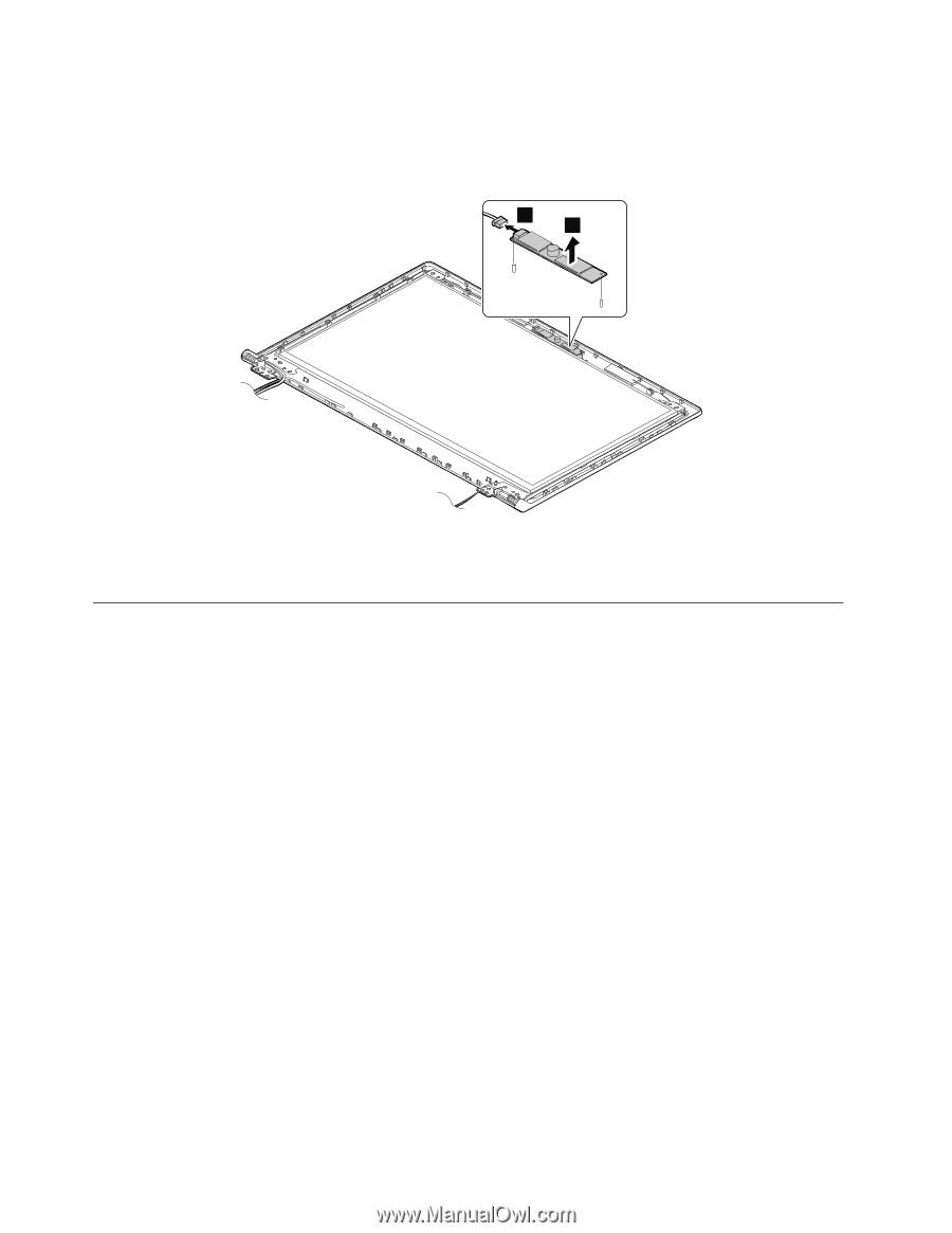
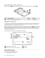
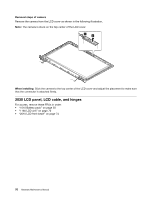
Removal steps of camera
Remove the camera from the LCD cover as shown in the following illustration.
Note:
The camera is stuck on the top center of the LCD cover.
1
2
When installing:
Stick the camera to the top center of the LCD cover and adjust the placement to make sure
that the connector is attached firmly.
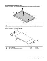
2030 LCD panel, LCD cable, and hinges
For access, remove these FRUs in order:
•
“1010 Battery pack” on page 50
•
“1180 LCD unit” on page 70
•
“2010 LCD front bezel” on page 74
76
Hardware Maintenance Manual