Lenovo E4325 Laptop Hardware Maintenance Manual - Lenovo E4325 - Page 76
LCD unit
 |
View all Lenovo E4325 Laptop manuals
Add to My Manuals
Save this manual to your list of manuals |
Page 76 highlights
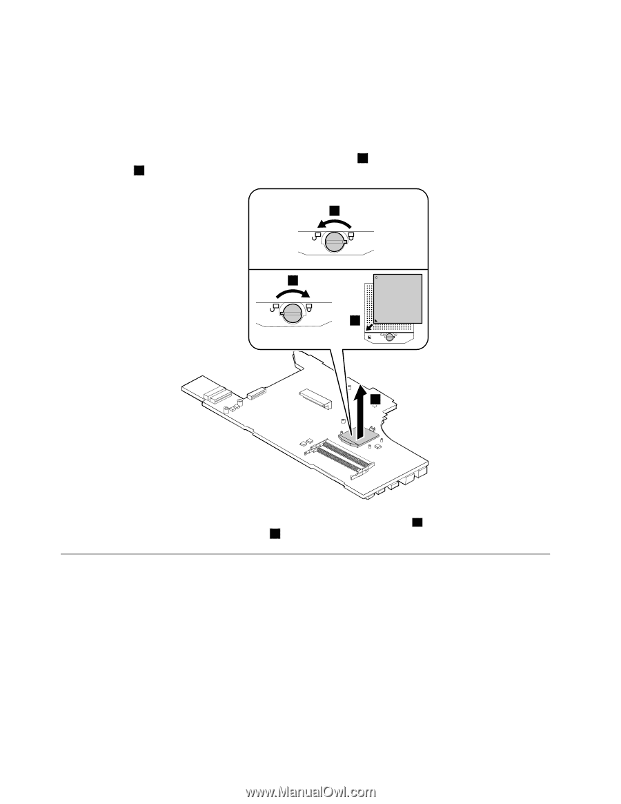
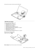
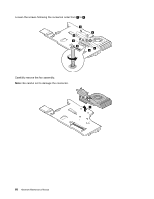
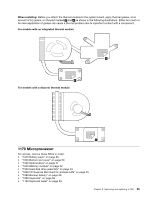
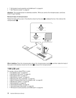
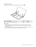
• "1150 System board assembly and USB board" on page 64 • "1160 Thermal module" on page 67 Attention: The microprocessor is extremely sensitive. When you service the microprocessor, avoid any kind of rough handling. Removal steps of microprocessor Rotate the head of the screw in the direction shown by the arrow 1 to release the lock, then remove the microprocessor 2 . 1 b a 2 When installing: Place the microprocessor above the microprocessor socket a , and then rotate the head of the screw in the direction shown by the arrow b to secure the microprocessor. 1180 LCD unit For access, remove these FRUs in order: • "1010 Battery pack" on page 50 • "1020 Bottom slot cover" on page 50 • "1030 Optical drive" on page 51 • "1040 Memory module" on page 52 • "1050 Hard disk drive assembly" on page 53 • "1060 PCI Express Mini Card for wireless LAN" on page 55 • "1080 Backup battery" on page 56 • "1090 Keyboard" on page 56 • "1100 Keyboard bezel" on page 59 • "1140 Input/output (I/O) board" on page 62 • "1150 System board assembly and USB board" on page 64 70 Hardware Maintenance Manual
-
 1
1 -
2
-
3
-
4
-
5
-
6
-
7
-
8
-
9
-
10
-
11
-
12
-
13
-
14
-
15
-
16
-
17
-
18
-
19
-
20
-
21
-
22
-
23
-
24
-
25
-
26
-
27
-
28
-
29
-
30
-
31
-
32
-
33
-
34
-
35
-
36
-
37
-
38
-
39
-
40
-
41
-
42
-
43
-
44
-
45
-
46
-
47
-
48
-
49
-
50
-
51
-
52
-
53
-
54
-
55
-
56
-
57
-
58
-
59
-
60
-
61
-
62
-
63
-
64
-
65
-
66
-
67
-
68
-
69
-
70
-
 71
71 -
 72
72 -
 73
73 -
 74
74 -
 75
75 -
 76
76 -
 77
77 -
 78
78 -
 79
79 -
 80
80 -
 81
81 -
82
-
83
-
84
-
85
-
86
-
87
-
88
 |
 |