Lenovo H520s Lenovo H520s Hardware Maintenance Manual - Page 37
Step 10. To install the new optical drive, drive straight out of the front of the drive bay. - 31
 |
View all Lenovo H520s manuals
Add to My Manuals
Save this manual to your list of manuals |
Page 37 highlights
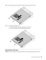
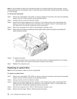
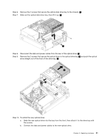
Step 6. Remove the 2 screws that secure the optical disk drive bay to the chassis. 1 Step 7. Slide out the optical disk drive bay, then lift it up. 2 2 1 Step 8. Disconnect the data and power cables from the rear of the optical drive. 3 Step 9. Remove the 2 screws that secure the optical drive to the optical drive bay 4 and push the optical drive straight out of the front of the drive bay. 5 5 3 4 Step 10. To install the new optical drive: a. Slide the new optical drive into the bay from the front, then attach it to the drive bay with the screws. b. Connect the data and power cables to the new optical drive. Chapter 8. Replacing hardware 31
-
 1
1 -
2
-
3
-
4
-
5
-
6
-
7
-
8
-
9
-
10
-
11
-
12
-
13
-
14
-
15
-
16
-
17
-
18
-
19
-
20
-
21
-
22
-
23
-
24
-
25
-
26
-
27
-
28
-
29
-
30
-
31
-
 32
32 -
 33
33 -
 34
34 -
 35
35 -
 36
36 -
 37
37 -
 38
38 -
 39
39 -
 40
40 -
 41
41 -
 42
42 -
43
-
44
-
45
-
46
-
47
-
48
-
49
-
50
-
51
-
52
-
53
-
54
-
55
-
56
-
57
-
58
-
59
 |
 |
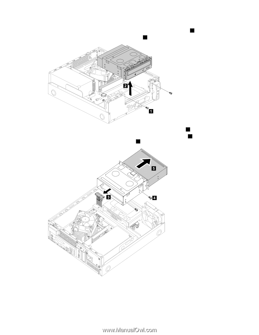
Step 6.
Remove the 2 screws that secure the optical disk drive bay to the chassis.
1
Step 7.
Slide out the optical disk drive bay, then lift it up.
2
Step 8.
Disconnect the data and power cables from the rear of the optical drive.
3
Step 9.
Remove the 2 screws that secure the optical drive to the optical drive bay
4
and push the optical
drive straight out of the front of the drive bay.
5
Step 10. To install the new optical drive:
a.
Slide the new optical drive into the bay from the front, then attach it to the drive bay with
the screws.
b.
Connect the data and power cables to the new optical drive.
Chapter 8
.
Replacing hardware
31