Lenovo IdeaCentre K210 K210 User's Guide - Page 8
Rear view of the chassis - memory
 |
View all Lenovo IdeaCentre K210 manuals
Add to My Manuals
Save this manual to your list of manuals |
Page 8 highlights
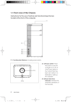
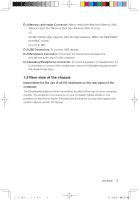
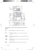
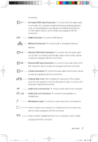
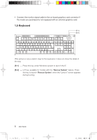
D-1 Memory card reader Connector: Able to read/write data from Memory Stick /Memory Stick Pro/ Memory Stick Duo /Memory Stick Pro Due xD SD/Mini SD/SD High Capacity /Mini SD High Capacity/ MMC/ RS-MMC/MMC plus/MMC mobile CF I/CF II/ MD. D-2 USB Connectors: To connect USB devices. D-3 Microphone Connector: To connect the microphone and pass the microphone audio input to the computer. D-4 Speakers/Headphones Connector: To connect speakers or headphones. If it is necessary to connect the headphones, remove the speaker plug and insert the headphones plug. 1.2 Rear view of the chassis Instructions for the use of all I/O interfaces on the rear panel of the computer. The following illustrations show connections located at the rear of some computer models. The locations of connectors on your computer will be similar to, but possibly not identical to these. Following the illustrations is a key that explains the symbol callouts used in the figures. 31033098_IdeaCentre K UG_EN.indd 3 User Guide 3 2008.2.20 6:40:03 PM
-
 1
1 -
2
-
 3
3 -
 4
4 -
 5
5 -
 6
6 -
 7
7 -
 8
8 -
 9
9 -
 10
10 -
 11
11 -
 12
12 -
 13
13 -
14
-
15
-
16
-
17
-
18
-
19
-
20
-
21
-
22
-
23
-
24
-
25
-
26
-
27
-
28
-
29
-
30
-
31
-
32
-
33
-
34
-
35
-
36
-
37
-
38
-
39
-
40
-
41
 |
 |
