Lenovo Miix 2 11 Hardware Maintenance Manual - Lenovo Miix 2 11 - Page 37
Volume board and power board, When installing
 |
View all Lenovo Miix 2 11 manuals
Add to My Manuals
Save this manual to your list of manuals |
Page 37 highlights
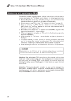
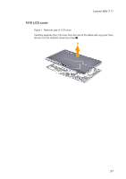
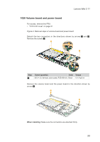
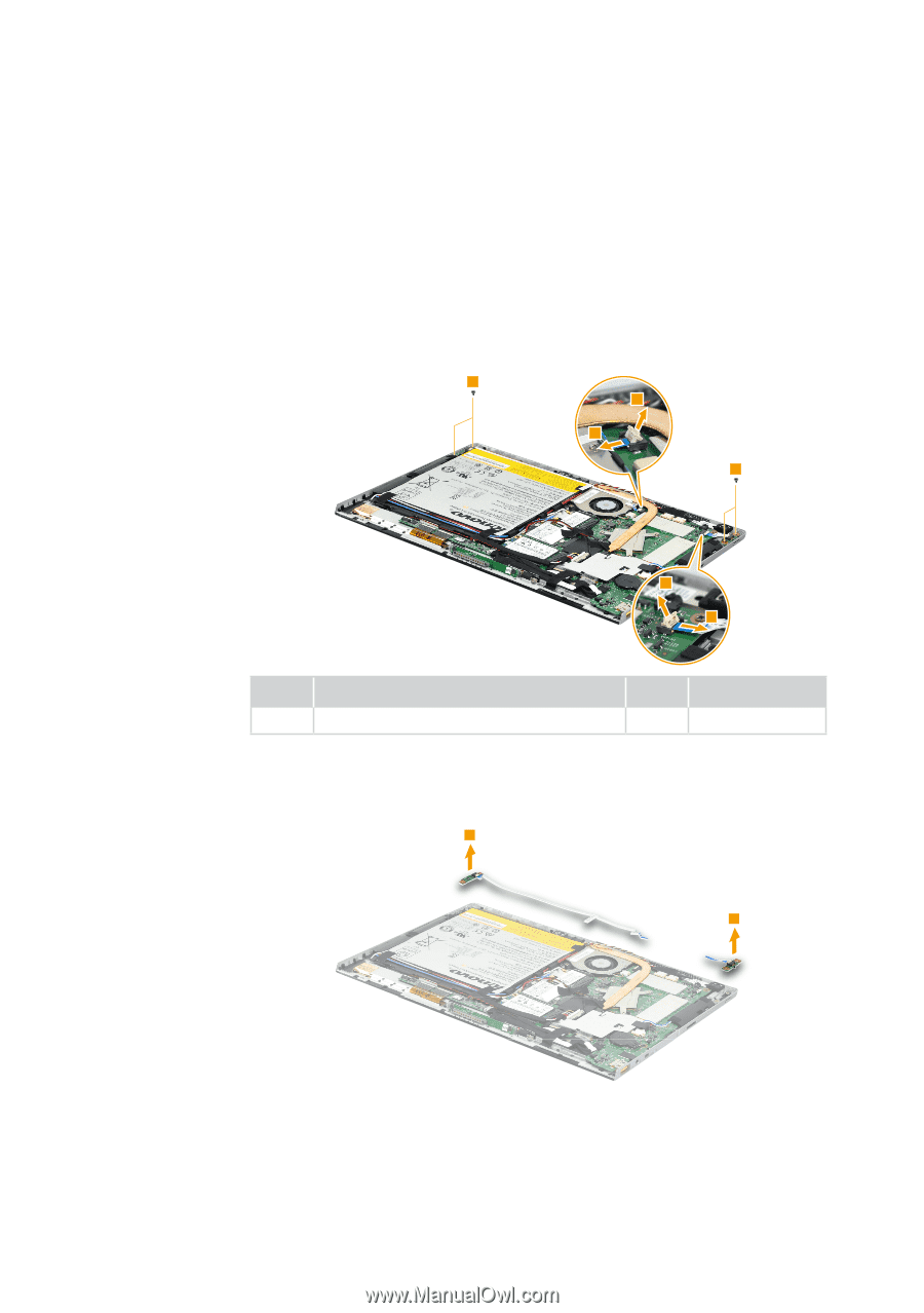
Lenovo Miix 2 11 1020 Volume board and power board For access, remove this FRU: • "1010 LCD cover" on page 31 Figure 2. Removal steps of volume board and power board Detach the two connectors in the directions shown by arrows 1 and 2. Remove the screws 3. 3 1 2 3 1 2 Step 3 Screw (quantity) Color Torque M2.0 × 3.0, flat-head, nylok-coated, PCB ASM (4) Black 1.6~2 kgf*cm Remove the volume board and the power board in the direction shown by arrows 4. 4 4 When installing: Make sure the connectors are attached firmly. 33
-
 1
1 -
2
-
3
-
4
-
5
-
6
-
7
-
8
-
9
-
10
-
11
-
12
-
13
-
14
-
15
-
16
-
17
-
18
-
19
-
20
-
21
-
22
-
23
-
24
-
25
-
26
-
27
-
28
-
29
-
30
-
31
-
 32
32 -
 33
33 -
 34
34 -
 35
35 -
 36
36 -
 37
37 -
 38
38 -
 39
39 -
 40
40 -
 41
41 -
 42
42 -
43
-
44
-
45
-
46
-
47
-
48
-
49
-
50
-
51
-
52
-
53
-
54
-
55
-
56
-
57
-
58
-
59
-
60
-
61
-
62
-
63
-
64
-
65
-
66
-
67
-
68
-
69
 |
 |
33
Lenovo Miix 2 11
1020 Volume board and power board
For access, remove this FRU:
•
“1010 LCD cover” on page 31
Figure 2. Removal steps of volume board and power board
Detach the two connectors in the directions shown by arrows
1
and
2
.
Remove the screws
3
.
3
3
2
2
1
1
Step
Screw (quantity)
Color
Torque
3
M2.0 × 3.0, flat-head, nylok-coated, PCB ASM (4)
Black
1.6~2 kgf*cm
Remove the volume board and the power board in the direction shown by
arrows
4
.
4
4
When installing:
Make sure the connectors are attached firmly.