Lenovo Miix 2 11 Hardware Maintenance Manual - Lenovo Miix 2 11 - Page 44
Wireless LAN card
 |
View all Lenovo Miix 2 11 manuals
Add to My Manuals
Save this manual to your list of manuals |
Page 44 highlights
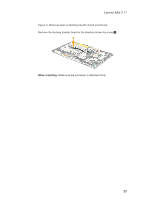
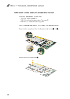
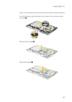
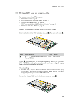
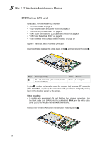
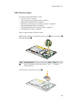
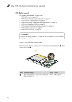
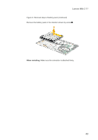
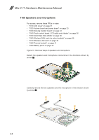
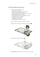
Miix 2 11 Hardware Maintenance Manual 1070 Wireless LAN card For access, remove these FRUs in order: • "1010 LCD cover" on page 31 • "1020 Volume board and power board" on page 33 • "1030 Docking transfer board" on page 34 • "1040 Touch control board, LCD cable and vibrator" on page 36 • "1050 Solid State Disk (SSD)" on page 38 • "1060 Wireless WAN card (on select models)" on page 39 Figure 7. Removal steps of wireless LAN card Disconnect the two wireless LAN cables (black, white) 1, and then remove the screw 2. 2 1 Step 2 Screw (quantity) M1.6 × 2, flat-head, nylok-coated, Card & Thermal ASM (1) Color Torque Silver 1.6~2 kgf*cm In step 1, unplug the jacks by using the removal tool antenna RF connector (P/N: 51078891), or pick up the connectors with your fingers and gently unplug them in the direction shown by the arrows. When installing: • In models with a wireless LAN card that has two antenna connectors, plug the black cable (1st) (MAIN) into the jack labeled MAIN, and the white cable (2nd) (AUX) into the jack labeled AUX on the card. Remove the wireless LAN card in the direction shown by arrow 3. 3 40
-
 1
1 -
2
-
3
-
4
-
5
-
6
-
7
-
8
-
9
-
10
-
11
-
12
-
13
-
14
-
15
-
16
-
17
-
18
-
19
-
20
-
21
-
22
-
23
-
24
-
25
-
26
-
27
-
28
-
29
-
30
-
31
-
32
-
33
-
34
-
35
-
36
-
37
-
38
-
 39
39 -
 40
40 -
 41
41 -
 42
42 -
 43
43 -
 44
44 -
 45
45 -
 46
46 -
 47
47 -
 48
48 -
 49
49 -
50
-
51
-
52
-
53
-
54
-
55
-
56
-
57
-
58
-
59
-
60
-
61
-
62
-
63
-
64
-
65
-
66
-
67
-
68
-
69
 |
 |