Lenovo PC 300GL Technical Information Manual 6272, 6282 - Page 21
Input/Output Controller, Diskette Drive Support, Serial Port
 |
View all Lenovo PC 300GL manuals
Add to My Manuals
Save this manual to your list of manuals |
Page 21 highlights
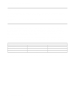
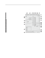
Chapter 2. System Board Features Input/Output Controller Control of the integrated input/output (I/O) ports and diskette drive controller is provided by a single chip, the National Semiconductor PC87307. This chip, which supports Plug and Play, controls the following features: Diskette drive support Serial port Parallel port Keyboard and mouse ports Infrared port General purpose I/O ports Real-time clock Advanced Power Management support The chip requires an external 24 MHz frequency. Diskette Drive Support A maximum of two diskette drives and one tape backup drive is supported on the system board. The actual number of diskette drives that can be installed is dependent upon the system unit size (the PC 300GL 6272 has three drive bays for installing devices and the PC 300GL 6282 has four drive bays for installing internal devices). The following is a list of devices that the diskette drive subsystem supports: 1.44 MB, 3.5" diskette drive 2.88 MB, 3.5" diskette drive 1.2 MB, 5.25" diskette drive One connector is provided on the system board for diskette drive support. For information on the connector pin assignments, see "Diskette Drive Connector" on page 35. Serial Port Integrated into the system board are two universal asynchronous receiver/transmitter (UART) serial ports. The serial ports include a 16-byte data, first-in first-out (FIFO) buffer, and have programmable baud rate generators. The serial ports are NS16450 and PC16550A compatible. For information on the connector pin assignments, see "Serial Port Connectors" on page 37. Note: Current loop interface is not supported. The following figure shows the serial port assignments used in configuration. Figure 4. Serial Port Assignments Port Assignment Serial 1 Serial 2 Serial 3 Serial 4 Address Range 03F8h-03FFh 02F8h-02FFh 03E8h-03FFh 02E8h-02FFh IRQ Level IRQ4 IRQ3 IRQ4 IRQ3 Chapter 2. System Board Features 9
-
 1
1 -
2
-
3
-
4
-
5
-
6
-
7
-
8
-
9
-
10
-
11
-
12
-
13
-
14
-
15
-
 16
16 -
 17
17 -
 18
18 -
 19
19 -
 20
20 -
 21
21 -
 22
22 -
 23
23 -
 24
24 -
 25
25 -
 26
26 -
27
-
28
-
29
-
30
-
31
-
32
-
33
-
34
-
35
-
36
-
37
-
38
-
39
-
40
-
41
-
42
-
43
-
44
-
45
-
46
-
47
-
48
-
49
-
50
-
51
-
52
-
53
-
54
-
55
-
56
-
57
-
58
-
59
-
60
-
61
-
62
-
63
-
64
-
65
-
66
-
67
-
68
-
69
-
70
-
71
-
72
 |
 |
