Lenovo PC 300GL Technical Information Manual 6272, 6282 - Page 26
Jumpers, Switches
 |
View all Lenovo PC 300GL manuals
Add to My Manuals
Save this manual to your list of manuals |
Page 26 highlights
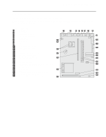
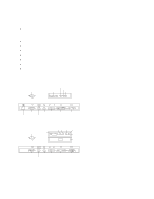
Chapter 2. System Board Features Jumpers Jumpers on the system board are used for custom configurations. The following figures show the description of pin numbers for specific jumpers. To locate these jumpers, see "System Board" on page 13. Figure 7. J6 CMOS Clear/Password Jumper Pins 1 and 2 2 and 3 Description Normal Clear CMOS/Password Switches The switches (SW1) are used for setting the microprocessor speed and diskette-write protection. The following figure shows the configuration of switches 1-4 for the different microprocessor speeds. Figure 8. Microprocessor Speed (SW1 1-4) Switch 100 MHz 120 MHz 133 MHz 1 Off On On 2 Off Off Off 3 Off On Off 4 On Off On 150 MHz On On On Off 166 MHz On On Off On 200 MHz Off On Off On 233 MHz Off Off Off On The following figure shows the configuration of switch 5 for disabling or enabling the Ethernet controller. Note: This switch is functional only on models with integrated/on-board Ethernet only. Figure 9. Ethernet Disable/Enable (SW1 5) Switch Enabled 5 On Disabled Off Note: This switch should not be used to disable the Ethernet controller under normal conditions. BIOS will disable it if selected in setup. This switch should only be used to aid in diagnosing problems. The following figure shows the configuration of switch 6 for diskette-write protection. Figure 10. Diskette-Write Protection (SW1 6) Switch Diskette Write-Enabled 6 Off Diskette Write-Protected On 14 Technical Information Manual
-
 1
1 -
2
-
3
-
4
-
5
-
6
-
7
-
8
-
9
-
10
-
11
-
12
-
13
-
14
-
15
-
16
-
17
-
18
-
19
-
20
-
 21
21 -
 22
22 -
 23
23 -
 24
24 -
 25
25 -
 26
26 -
 27
27 -
 28
28 -
 29
29 -
 30
30 -
 31
31 -
32
-
33
-
34
-
35
-
36
-
37
-
38
-
39
-
40
-
41
-
42
-
43
-
44
-
45
-
46
-
47
-
48
-
49
-
50
-
51
-
52
-
53
-
54
-
55
-
56
-
57
-
58
-
59
-
60
-
61
-
62
-
63
-
64
-
65
-
66
-
67
-
68
-
69
-
70
-
71
-
72
 |
 |
