Lenovo PC 300GL Technical Information Manual 6272, 6282 - Page 25
Physical Layout, System Board
 |
View all Lenovo PC 300GL manuals
Add to My Manuals
Save this manual to your list of manuals |
Page 25 highlights
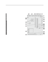
Chapter 2. System Board Features Physical Layout The system board might look slightly different from the one shown. Note: A diagram of the system board, including switch and jumper settings, is attached to the underside of the computer cover. System Board 1 Monitor port 2 Parallel port 3 Universal Serial Bus Port 4 Universal Serial Bus Port 5 Mouse port 6 Keyboard port 7 Serial port 1 8 Ethernet port (some models only) 9 Serial port 2 connector 1 Main power connector (J2) 11 Clear CMOS jumper (J6) 12 Diskette drive connector (J3) 13 Primary IDE connector (J12) 14 Secondary IDE connector (J13) 15 Power LED connector (J8) 16 DIMM sockets (J14 and J16) 17 Configuration switch (SW1) 18 3.3 V power connector (J22) 19 Fan connector (J18) 2 LAN activity LED connector (J24) (some models only) 21 COAST cache module socket (J26) 22 Pentium processor socket 7 23 Riser connector 24 Battery 25 Video RAM expansion sockets (U20 and U25) 26 Wake on LAN connector (J28) 27 Wakeup on Modem/Ring connector (J27) Chapter 2. System Board Features 13
-
 1
1 -
2
-
3
-
4
-
5
-
6
-
7
-
8
-
9
-
10
-
11
-
12
-
13
-
14
-
15
-
16
-
17
-
18
-
19
-
 20
20 -
 21
21 -
 22
22 -
 23
23 -
 24
24 -
 25
25 -
 26
26 -
 27
27 -
 28
28 -
 29
29 -
 30
30 -
31
-
32
-
33
-
34
-
35
-
36
-
37
-
38
-
39
-
40
-
41
-
42
-
43
-
44
-
45
-
46
-
47
-
48
-
49
-
50
-
51
-
52
-
53
-
54
-
55
-
56
-
57
-
58
-
59
-
60
-
61
-
62
-
63
-
64
-
65
-
66
-
67
-
68
-
69
-
70
-
71
-
72
 |
 |
