Lenovo ThinkCentre A50 Hardware Maintenance Manual - Page 98
Identifying, parts, system, board, Removing, replacing, memory, module
 |
View all Lenovo ThinkCentre A50 manuals
Add to My Manuals
Save this manual to your list of manuals |
Page 98 highlights
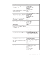
Identifying parts on the system board 1 Hard disk drive connector 2 Optical drive connector 3 PCI riser connector 4 12v power connector 5 Power connector 6 Front fan connector 7 Microprocessor 8 Speaker connector 9 Memory connector 1 10 Memory connector 2 11 Rear fan connector 12 SATA connector 13 Clear CMOS/Recovery jumper 14 Battery Removing and replacing a memory module 1. Open the cover. See "Opening the cover" on page 90. 2. Locate the memory connectors. See "Identifying parts on the system board." 3. Open the retaining clips and remove the failing memory module. 92 Hardware Maintenance Manual
-
 1
1 -
2
-
3
-
4
-
5
-
6
-
7
-
8
-
9
-
10
-
11
-
12
-
13
-
14
-
15
-
16
-
17
-
18
-
19
-
20
-
21
-
22
-
23
-
24
-
25
-
26
-
27
-
28
-
29
-
30
-
31
-
32
-
33
-
34
-
35
-
36
-
37
-
38
-
39
-
40
-
41
-
42
-
43
-
44
-
45
-
46
-
47
-
48
-
49
-
50
-
51
-
52
-
53
-
54
-
55
-
56
-
57
-
58
-
59
-
60
-
61
-
62
-
63
-
64
-
65
-
66
-
67
-
68
-
69
-
70
-
71
-
72
-
73
-
74
-
75
-
76
-
77
-
78
-
79
-
80
-
81
-
82
-
83
-
84
-
85
-
86
-
87
-
88
-
89
-
90
-
91
-
92
-
 93
93 -
 94
94 -
 95
95 -
 96
96 -
 97
97 -
 98
98 -
 99
99 -
 100
100 -
 101
101 -
 102
102 -
 103
103 -
104
-
105
-
106
-
107
-
108
-
109
-
110
-
111
-
112
-
113
-
114
-
115
-
116
-
117
-
118
-
119
-
120
-
121
-
122
-
123
-
124
-
125
-
126
-
127
-
128
-
129
-
130
-
131
-
132
-
133
-
134
-
135
-
136
-
137
-
138
-
139
-
140
-
141
-
142
-
143
-
144
-
145
-
146
-
147
-
148
-
149
-
150
-
151
-
152
-
153
-
154
-
155
-
156
-
157
-
158
-
159
-
160
-
161
-
162
-
163
-
164
 |
 |

Identifying
parts
on
the
system
board
±1²
Hard
disk
drive
connector
±8²
Speaker
connector
±2²
Optical
drive
connector
±9²
Memory
connector
1
±3²
PCI
riser
connector
±10²
Memory
connector
2
±4²
12v
power
connector
±11²
Rear
fan
connector
±5²
Power
connector
±12²
SATA
connector
±6²
Front
fan
connector
±13²
Clear
CMOS/Recovery
jumper
±7²
Microprocessor
±14²
Battery
Removing
and
replacing
a
memory
module
1.
Open
the
cover.
See
“Opening
the
cover”
on
page
90.
2.
Locate
the
memory
connectors.
See
“Identifying
parts
on
the
system
board.”
3.
Open
the
retaining
clips
and
remove
the
failing
memory
module.
92
Hardware
Maintenance
Manual