Lenovo ThinkPad 560E TP 560Z Technical Reference Manual - Page 27
External Connector
 |
View all Lenovo ThinkPad 560E manuals
Add to My Manuals
Save this manual to your list of manuals |
Page 27 highlights
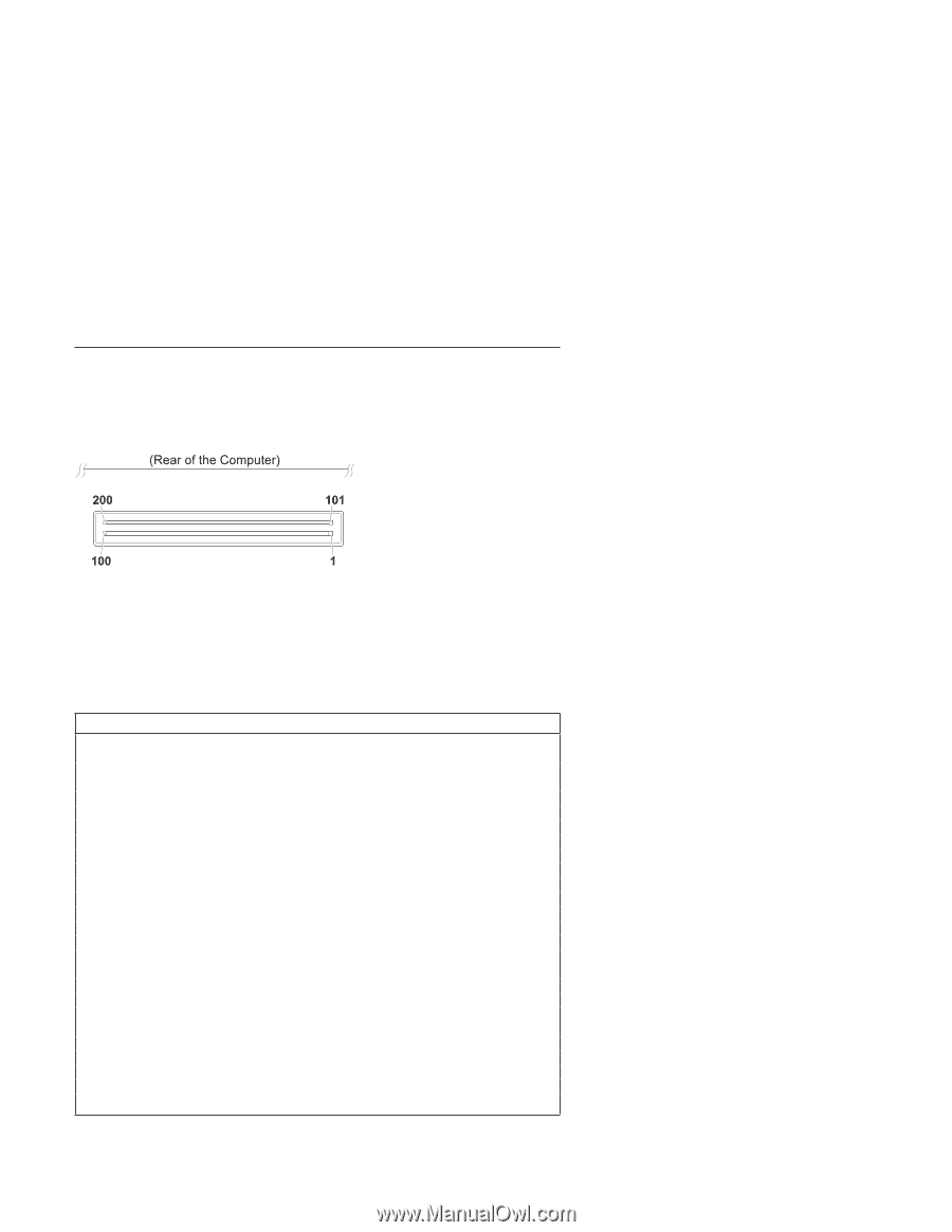
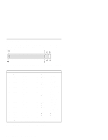
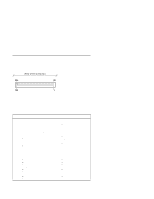
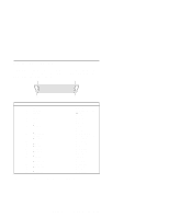
External Connector The Port Replicator is connected through the 200-pin external connector at the bottom of the computer. This connector is installed on the system board and has the following pin assignments: Type Legend: A: Audio signal F: Diskette drive signal G: Ground I: Interrupt request signal J: Joy stick signal K: Keyboard/Mouse signal PB: Serial port signal PC: Power control signal PM: Power Management signal PR: Parallel port signal PW: Power line S: Serial port signal U: USB signal V: Video signal Pin Signal 1 Ground Type G 2 Suspend Power PC Good 3 ac/dc Power PW 4 ac/dc Power PW 5 ac/dc Power PW 6 ac/dc Power PW 7 −Suspend Status PM 8 Ground G 9 Line In Left A 10 +5V PW 11 Line Out Left A 12 Analog Ground A 13 Ground G 14 Data Rate Select F 1 15 −Drive Select 1 F 16 −Docking SMI PM 17 −MOTOR G ENABLE 0 18 −Direction In G 19 −Step G 20 Write Data G 21 −Write Enable G 22 −Head 1 Select G Pin Signal Type 23 Docking Type PM Select 24 −External Power PC Good 25 Mouse Data K 26 Mouse Clock K 27 Ground G 28 −PME PM 29 USB_OC1 U 30 Ground G 31 −Ring Indicator S 32 Clear to Send S 33 Request to Send S 34 Data Set Ready S 35 Ground G 36 Ground G 37 −AUTO FD XT PR 38 −ERROR PR 39 −INIT PR 40 −SLCT IN PR 41 Data Bit 4 PR 42 Data Bit 6 PR 43 −ACK PR 44 PE PR Figure 2-7 (Part 1 of 3). 200-Pin External Connector Pin Assignments ThinkPad 560Z System Board 2-9
-
 1
1 -
2
-
3
-
4
-
5
-
6
-
7
-
8
-
9
-
10
-
11
-
12
-
13
-
14
-
15
-
16
-
17
-
18
-
19
-
20
-
21
-
 22
22 -
 23
23 -
 24
24 -
 25
25 -
 26
26 -
 27
27 -
 28
28 -
 29
29 -
 30
30 -
 31
31 -
 32
32 -
33
-
34
-
35
-
36
-
37
-
38
-
39
-
40
-
41
-
42
-
43
-
44
-
45
-
46
-
47
-
48
-
49
-
50
-
51
-
52
-
53
-
54
-
55
-
56
-
57
-
58
-
59
-
60
-
61
-
62
-
63
-
64
-
65
-
66
-
67
-
68
-
69
-
70
-
71
-
72
-
73
-
74
-
75
-
76
-
77
-
78
-
79
-
80
-
81
-
82
-
83
-
84
-
85
-
86
-
87
-
88
-
89
-
90
-
91
-
92
-
93
-
94
-
95
-
96
-
97
-
98
-
99
-
100
-
101
-
102
-
103
-
104
-
105
-
106
-
107
-
108
-
109
-
110
-
111
-
112
-
113
-
114
-
115
-
116
-
117
-
118
-
119
-
120
-
121
-
122
-
123
-
124
-
125
-
126
-
127
-
128
-
129
-
130
-
131
-
132
-
133
-
134
 |
 |