Lenovo ThinkPad E450 (English) Hardware Maintenance Manual - ThinkPad E450, E4 - Page 92
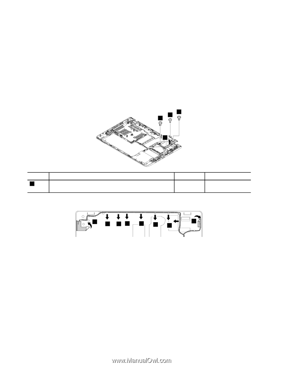
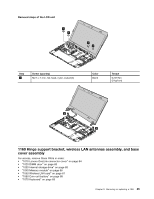
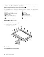
Remove the screws that secure the hinge support bracket. Then remove the hinge support bracket.
 |
View all Lenovo ThinkPad E450 manuals
Add to My Manuals
Save this manual to your list of manuals |
Page 92 highlights
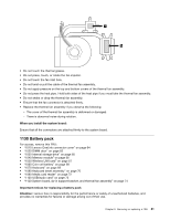
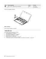
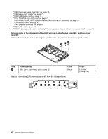
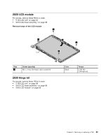
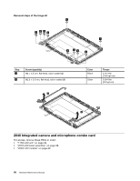
• "1080 Keyboard bezel assembly" on page 70 • "1090 Media card reader" on page 72 • "1100 USB/audio card" on page 73 • "1110 ThinkPad-logo-LED card" on page 73 • "1120 System board, dc-in support bracket, and thermal fan assembly" on page 74 • "1130 Battery pack" on page 81 • "1140 Speaker assembly" on page 83 • "1150 LCD unit" on page 84 • "1160 Hinge support bracket, wireless LAN antennas assembly, and base cover assembly" on page 85 Removal steps of the hinge support bracket, wireless LAN antennas assembly, and base cover assembly Remove the screws that secure the hinge support bracket. Then remove the hinge support bracket. 1 1 1 2 Step 1 Screw (quantity) M2 × 3 mm, wafer-head, nylon-coated (3) Color Black Release the wireless LAN antennas assembly from the tabs as shown. Torque 0.181 Nm (1.85 kgf-cm) 4 3 33 3 3 3 4 86 Hardware Maintenance Manual
-
 1
1 -
2
-
3
-
4
-
5
-
6
-
7
-
8
-
9
-
10
-
11
-
12
-
13
-
14
-
15
-
16
-
17
-
18
-
19
-
20
-
21
-
22
-
23
-
24
-
25
-
26
-
27
-
28
-
29
-
30
-
31
-
32
-
33
-
34
-
35
-
36
-
37
-
38
-
39
-
40
-
41
-
42
-
43
-
44
-
45
-
46
-
47
-
48
-
49
-
50
-
51
-
52
-
53
-
54
-
55
-
56
-
57
-
58
-
59
-
60
-
61
-
62
-
63
-
64
-
65
-
66
-
67
-
68
-
69
-
70
-
71
-
72
-
73
-
74
-
75
-
76
-
77
-
78
-
79
-
80
-
81
-
82
-
83
-
84
-
85
-
86
-
 87
87 -
 88
88 -
 89
89 -
 90
90 -
 91
91 -
 92
92 -
 93
93 -
 94
94 -
 95
95 -
 96
96 -
 97
97 -
98
-
99
-
100
-
101
-
102
-
103
-
104
 |
 |