Lenovo ThinkPad i Series 1400 Hardware Maintenance Manual (August 1999) - Page 170
M2.5 x, black, kgf-cm, nylock, paste, Make sure you use the correct screw for replacement
 |
View all Lenovo ThinkPad i Series 1400 manuals
Add to My Manuals
Save this manual to your list of manuals |
Page 170 highlights
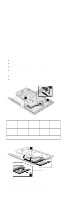
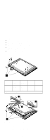
Fan Assembly "Battery Assembly" on page 142 "Keyboard" on page 145 "Processor Thermal Plate" on page 147 "RTC Battery, Processor EMI Shield and Hard Disk Drive" on page 148 "LCD Assembly" on page 151 "Upper Cover (Keyboard Bezel)" on page 153 3 2 1 4 Step Size (Quantity) Head & Color Torque Memo 2 M2.5 x Bind 3.2 w/ 6L (2) head, kgf-cm nylock black paste 4 M2.5 x Bind 3.2 w/ 4L (2) head, kgf-cm nylock black paste Note: Make sure you use the correct screw for replacement. 162 ThinkPad i Series 1400 HMM
-
 1
1 -
2
-
3
-
4
-
5
-
6
-
7
-
8
-
9
-
10
-
11
-
12
-
13
-
14
-
15
-
16
-
17
-
18
-
19
-
20
-
21
-
22
-
23
-
24
-
25
-
26
-
27
-
28
-
29
-
30
-
31
-
32
-
33
-
34
-
35
-
36
-
37
-
38
-
39
-
40
-
41
-
42
-
43
-
44
-
45
-
46
-
47
-
48
-
49
-
50
-
51
-
52
-
53
-
54
-
55
-
56
-
57
-
58
-
59
-
60
-
61
-
62
-
63
-
64
-
65
-
66
-
67
-
68
-
69
-
70
-
71
-
72
-
73
-
74
-
75
-
76
-
77
-
78
-
79
-
80
-
81
-
82
-
83
-
84
-
85
-
86
-
87
-
88
-
89
-
90
-
91
-
92
-
93
-
94
-
95
-
96
-
97
-
98
-
99
-
100
-
101
-
102
-
103
-
104
-
105
-
106
-
107
-
108
-
109
-
110
-
111
-
112
-
113
-
114
-
115
-
116
-
117
-
118
-
119
-
120
-
121
-
122
-
123
-
124
-
125
-
126
-
127
-
128
-
129
-
130
-
131
-
132
-
133
-
134
-
135
-
136
-
137
-
138
-
139
-
140
-
141
-
142
-
143
-
144
-
145
-
146
-
147
-
148
-
149
-
150
-
151
-
152
-
153
-
154
-
155
-
156
-
157
-
158
-
159
-
160
-
161
-
162
-
163
-
164
-
 165
165 -
 166
166 -
 167
167 -
 168
168 -
 169
169 -
 170
170 -
 171
171 -
 172
172 -
 173
173 -
 174
174 -
 175
175 -
176
-
177
-
178
-
179
-
180
-
181
-
182
-
183
-
184
-
185
-
186
-
187
-
188
-
189
-
190
-
191
-
192
-
193
-
194
-
195
-
196
-
197
-
198
-
199
-
200
-
201
-
202
-
203
-
204
 |
 |

Fan Assembly
±
“Battery Assembly” on page
142
±
“Keyboard” on page
145
±
“Processor Thermal Plate” on page
147
±
“RTC Battery, Processor EMI Shield and Hard Disk
Drive” on page
148
±
“LCD Assembly” on page
151
±
“Upper Cover (Keyboard Bezel)” on page
153
3
2
1
4
Step
Size
(Quan-
tity)
Head &
Color
Torque
Memo
2
M2.5 x
6L (2)
Bind
head,
black
3.2
kgf-cm
w/
nylock
paste
4
M2.5 x
4L (2)
Bind
head,
black
3.2
kgf-cm
w/
nylock
paste
Note:
Make sure you use the correct screw for replacement.
162
ThinkPad i Series 1400 HMM