Lenovo U130 Laptop Lenovo 3000 C300 Hardware Maintenance Manual - Page 53
Replacing the system fan
 |
View all Lenovo U130 Laptop manuals
Add to My Manuals
Save this manual to your list of manuals |
Page 53 highlights
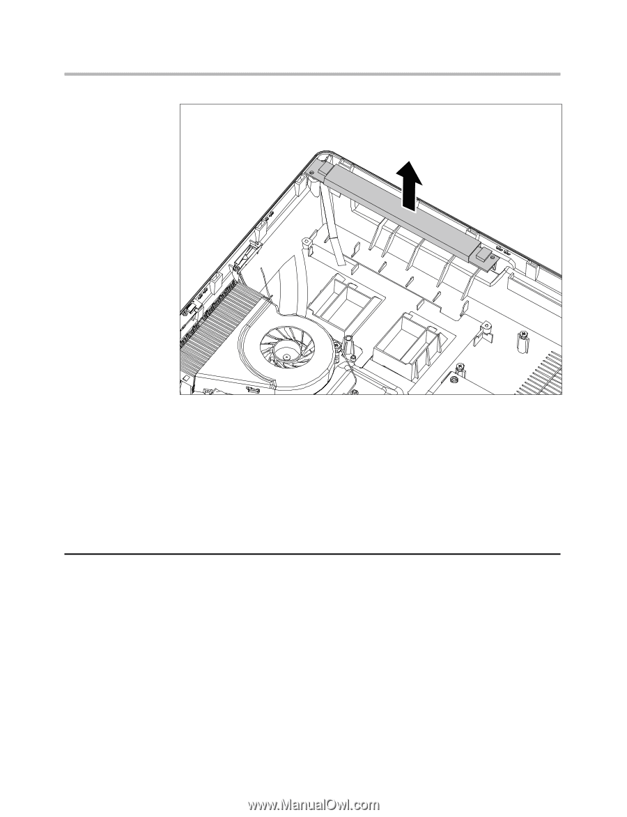
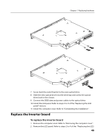
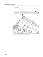
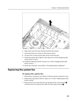
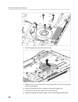
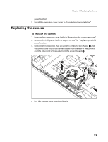
Chapter 7. Replacing hardware 6. Align then insert the new inverter board to the chassis. 7. Screw back the two screws on the inverter board. 8. Connect the inverter board cable to the inverter board. 9. Install the optical drive. Refer to the steps 8 to 9 of the "Replacing the optical drive" section. 10. Install the LCD panel. Refer to steps 5 to 6 of the "Replacing the LCD panel" section. 11. Install the computer cover. Refer to "Completing the installation" . Replacing the system fan To replace the system fan 1. Remove the computer cover. Refer to "Removing the computer cover" . 2. Remove the LCD panel. Refer to steps 2 to 4 of the "Replacing the LCD panel section" . 3. Remove the four screws that secure the system fan to the chassis 1 and disconnect the system fan cable from the system board 2. 51
-
 1
1 -
2
-
3
-
4
-
5
-
6
-
7
-
8
-
9
-
10
-
11
-
12
-
13
-
14
-
15
-
16
-
17
-
18
-
19
-
20
-
21
-
22
-
23
-
24
-
25
-
26
-
27
-
28
-
29
-
30
-
31
-
32
-
33
-
34
-
35
-
36
-
37
-
38
-
39
-
40
-
41
-
42
-
43
-
44
-
45
-
46
-
47
-
 48
48 -
 49
49 -
 50
50 -
 51
51 -
 52
52 -
 53
53 -
 54
54 -
 55
55 -
 56
56 -
 57
57 -
 58
58 -
59
-
60
-
61
-
62
-
63
-
64
-
65
-
66
-
67
-
68
-
69
-
70
-
71
 |
 |