Lenovo U130 Laptop Lenovo 3000 C300 Hardware Maintenance Manual - Page 61
Replacing the system board
 |
View all Lenovo U130 Laptop manuals
Add to My Manuals
Save this manual to your list of manuals |
Page 61 highlights
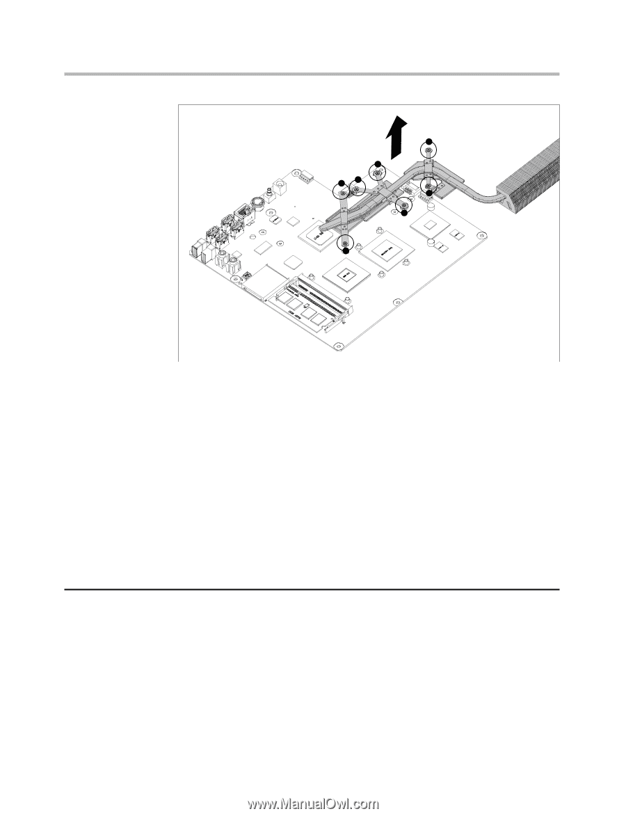
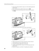
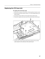
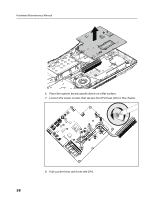
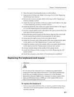
Chapter 7. Replacing hardware 3 5 2 7 6 1 4 9. Set the new heat sink on the CPU, aligning the seven screws in the heat sink with the screw sockets in the chassis. 10. Tighten the seven screws on the heat sink. 11. Connect related cables to the underside of the system board. 12. Place the system board upside down. 13. Place the system board into the chassis, aligning the screw holes on the system board with the mounting holes on the chassis. 14. Screw back the eight screws on the system board. 15. Connect related cables to the upside of the system board. 16. Install the LCD panel. Refer to steps 5 to 6 of the "Replacing the LCD panel" section. 17. Install the computer cover. Refer to "Completing the installation" . Replacing the system board To replace the system board 1. Remove the computer cover. Refer to "Removing the computer cover" . 2. Remove the LCD panel. Refer to steps 2 to 4 of the "Replacing the LCD panel section" . 3. Remove the wireless card. Refer to the steps 3 to 5 of the "Replacing the wireless card" section. 4. Remove the TV tuner card. Refer to the steps 3 to 5 of the "Replacing the TV tuner card" section. 59
-
 1
1 -
2
-
3
-
4
-
5
-
6
-
7
-
8
-
9
-
10
-
11
-
12
-
13
-
14
-
15
-
16
-
17
-
18
-
19
-
20
-
21
-
22
-
23
-
24
-
25
-
26
-
27
-
28
-
29
-
30
-
31
-
32
-
33
-
34
-
35
-
36
-
37
-
38
-
39
-
40
-
41
-
42
-
43
-
44
-
45
-
46
-
47
-
48
-
49
-
50
-
51
-
52
-
53
-
54
-
55
-
 56
56 -
 57
57 -
 58
58 -
 59
59 -
 60
60 -
 61
61 -
 62
62 -
 63
63 -
 64
64 -
 65
65 -
 66
66 -
67
-
68
-
69
-
70
-
71
 |
 |