| Section |
Page |
| Table of contents |
5 |
| Notices and safety information |
7 |
| Laser notice |
7 |
| Laser |
7 |
| Avis relatif à l’utilisation de laser |
7 |
| Avvertenze sui prodotti laser |
7 |
| Avisos sobre el láser |
8 |
| Declaração sobre Laser |
8 |
| Laserinformatie |
8 |
| Lasermeddelelse |
8 |
| Huomautus laserlaitteesta |
9 |
| Laser-notis |
9 |
| Laser-melding |
9 |
| Avís sobre el Làser |
9 |
| Safety information |
11 |
| Consignes de sécurité |
11 |
| Norme di sicurezza |
11 |
| Sicherheitshinweise |
12 |
| Pautas de Seguridad |
12 |
| Informações de Segurança |
12 |
| Informació de Seguretat |
13 |
| Preface |
14 |
| Definitions |
14 |
| 1. General information |
15 |
| Models |
15 |
| Maintenance approach |
15 |
| Overview of the operator panel |
16 |
| Specifications |
17 |
| Tips on preventing jams |
21 |
| Tools |
22 |
| Acronyms |
23 |
| 2. Diagnostic information |
25 |
| Start |
25 |
| Power-On Self Test (POST) sequence |
26 |
| Light patterns and error messages |
26 |
| Ready/Power Saver |
28 |
| l |
28 |
| Busy |
28 |
| W |
28 |
| Hex Trace Ready |
28 |
| x |
28 |
| Waiting |
29 |
| l |
29 |
| Flushing/Resolution reduced |
29 |
| W |
29 |
| Not ready |
29 |
| Close door |
30 |
| Insufficient collation area/Insufficient memory |
30 |
| Cancel job/Reset printer |
30 |
| l |
30 |
| l |
30 |
| l |
30 |
| l |
30 |
| Load print media |
31 |
| l |
31 |
| Load manual feeder |
31 |
| l |
31 |
| Toner low |
31 |
| l |
31 |
| Toner cartridge region mismatch |
32 |
| l |
32 |
| Photoconductor kit life warning |
32 |
| W |
32 |
| Replace photoconductor (printer hard stop) |
32 |
| W |
32 |
| Programming engine code/Programming system code |
33 |
| l |
33 |
| l |
33 |
| l |
33 |
| Invalid engine code/Invalid network code |
33 |
| l |
33 |
| Service error |
33 |
| W |
33 |
| W |
33 |
| W |
33 |
| W |
33 |
| Printer error |
34 |
| Paper jam printer error |
34 |
| l |
34 |
| Short media |
34 |
| Output bin full |
35 |
| W |
35 |
| Paper jam at the input sensor |
38 |
| l |
38 |
| l |
38 |
| Paper jam in the manual feeder |
38 |
| l |
38 |
| l |
38 |
| l |
38 |
| Paper jams between the input and exit sensors |
38 |
| l |
38 |
| l |
38 |
| Paper jams as a printed job exits the printer |
38 |
| l |
38 |
| l |
38 |
| Paper jam in the 250-sheet tray |
39 |
| l |
39 |
| l |
39 |
| l |
39 |
| Paper jam in the 550-sheet drawer |
39 |
| l |
39 |
| l |
39 |
| l |
39 |
| Paper jam (duplex) |
39 |
| Paper jam (duplex front) |
39 |
| Paper jam (duplex rear) |
40 |
| l |
40 |
| W |
40 |
| Paper jam (duplex - unknown location) |
40 |
| l |
40 |
| W |
40 |
| Paper jam (duplex - unsupported size) |
40 |
| l |
40 |
| W |
40 |
| Complex page |
41 |
| l |
41 |
| Insufficient collation area |
41 |
| l |
41 |
| Network interface errors |
42 |
| l |
42 |
| Resource save off - deficient memory |
42 |
| l |
42 |
| Font error |
42 |
| Insufficient defrag memory |
43 |
| ENA connection lost |
43 |
| W |
43 |
| Host interface disabled |
43 |
| W |
43 |
| Memory full |
44 |
| l |
44 |
| Short media |
44 |
| l |
44 |
| Invalid engine code |
44 |
| l |
44 |
| Invalid network code |
45 |
| l |
45 |
| Toner cartridge region mismatch |
45 |
| l |
45 |
| Change toner cartridge/invalid refill |
45 |
| W |
45 |
| l |
45 |
| Missing/Defective toner cartridge |
46 |
| l |
46 |
| l |
46 |
| Unsupported toner cartridge |
46 |
| l |
46 |
| Too many options attached |
46 |
| Unsupported flash option |
47 |
| Service primary code |
48 |
| W |
48 |
| Service secondary error codes |
48 |
| Service tertiary error codes |
49 |
| Controller software |
49 |
| Transfer roll or tray 2 |
49 |
| Fuser, fan, or toner sensor error |
50 |
| Printhead, transport motor, or RIP/engine communication error |
51 |
| NVRAM failure |
52 |
| Network error |
52 |
| Messages and error codes |
53 |
| Symptom tables |
61 |
| Service checks |
63 |
| 1. Power to the LVPS/HVPS |
63 |
| 2. Power from the LVPS/HVPS to the controller card |
63 |
| 3. Cables are plugged in correctly, especially for the operator panel. The printer will not power-up without a functioning operator panel. |
63 |
| 4. The controller card assembly. |
63 |
| 5. The operator panel. See “Operator panel service check” on page 3-43. |
63 |
| 1. Turn the printer off. |
63 |
| 2. Disconnect the LVPS/HVPS cable from the controller card at J19. |
63 |
| 3. Turn the printer on. |
63 |
| 4. Verify +24 V dc on positions 8 and 9 of the cable connector. |
63 |
| 5. If voltage is correct, check the continuity in the other conductors of the cable. If the cable is good, check the connectors to the controller board. |
63 |
| 6. Verify that pins 7 and 12 on both the cable and the card connector are grounded. |
63 |
| 7. If grounds are not correct on the cable, but the cable posses continuity otherwise, check the LVPS/HVPS. |
63 |
| 8. If the grounds are not correct on the controller card, replace the controller card. (Check with one probe on the connector pin and the other on the card’s ground plane found at each screw head.) |
63 |
| Paper jam error indication during POST |
67 |
| Media picks during POST and/or continuously |
67 |
| Media picks but stops halfway through the printer |
68 |
| Media never picks |
68 |
| Media occasionally mispicks or picks multiple sheets at once |
68 |
| Media skews |
69 |
| Media “trees,” wrinkles, stacks poorly, or curls |
69 |
| Blank page |
70 |
| Black page |
71 |
| Heavy background |
71 |
| Partial blank image/white spots (no repeating pattern) |
72 |
| Variation in image density horizontally across page |
72 |
| Poor fusing of image |
72 |
| Light print |
73 |
| White or black lines or bands |
73 |
| Toner on back of page |
73 |
| Solving print quality problems |
74 |
| 3. Diagnostic aids |
79 |
| Accessing service menus |
79 |
| 1. Turn off the printer. |
79 |
| 2. Open the front access cover and turn on the printer while pressing and holding. |
79 |
| 3. Close the cover once thelight displays. |
79 |
| 1. Turn off the printer. |
79 |
| 2. Open the front access cover and press and holdwhile turning on the printer. |
79 |
| 3. Close the cover when the light displays. |
79 |
| Configuration Menu printout sample |
80 |
| Diagnostics mode printout sample |
81 |
| Configuration menu selections |
82 |
| Diagnostics mode selections |
86 |
| Adjustment procedures |
87 |
| Printhead assembly electronic adjustment |
87 |
| Printhead assembly mechanical adjustment |
91 |
| 4. Repair information |
93 |
| Handling ESD-sensitive parts |
93 |
| Removal procedures |
93 |
| Front access cover removal |
94 |
| Left side cover removal |
96 |
| Right side cover removal |
97 |
| Rear cover removal |
98 |
| Top cover removal |
99 |
| Auto comp removal |
101 |
| Auto comp clutch removal |
102 |
| Auto comp drive shaft assembly removal |
103 |
| Bezel removal |
104 |
| Controller card removal |
105 |
| Cover open sensor removal |
107 |
| Developer drive coupling assembly removal |
108 |
| Duplex removal |
110 |
| a. Remove the screw (A) and the screw (B) at the controller shield. |
110 |
| b. Remove the screw (C) opposite from screw (B) on the other side of the printer. |
110 |
| Duplex gear drive |
112 |
| Fan removal |
113 |
| Flag removal (top cover right) |
113 |
| Fuser removal |
114 |
| Fuser power cable removal |
116 |
| Link developer drive and access door removal |
117 |
| LVPS/HVPS card assembly removal |
118 |
| Main motor drive removal |
120 |
| Manual feed sensor removal |
122 |
| Manual paper feed clutch |
123 |
| Manual feed solenoids |
124 |
| Media level indicator removal |
125 |
| Narrow media sensor removal |
127 |
| Operator panel removal |
128 |
| Paper exit guide assembly removal |
129 |
| Paper feed rollers (autocompensator tires) removal |
130 |
| Paper input and duplex sensor removal |
131 |
| Printhead removal |
132 |
| Reversing solenoid removal |
133 |
| Toner level sensor removal |
133 |
| Transfer roll removal |
134 |
| Tray 2 auto comp tire removal |
135 |
| Upper front frame group removal |
136 |
| Wear strip removal (tray 1) |
138 |
| Wear strip removal (tray 2) |
138 |
| 5. Locations and connections |
141 |
| Locations |
141 |
| Connectors |
144 |
| 6. Preventive maintenance |
145 |
| Safety inspection guide |
145 |
| Lubrication specifications |
145 |
| Maintenance kits |
145 |
| 7. Parts Catalog |
147 |
| How to use this parts catalog |
147 |
| Assembly 1: Covers |
148 |
| Assembly 1: Covers |
149 |
| 1-1 |
149 |
| 40X5069 |
149 |
| 1 |
149 |
| 1 |
149 |
| 2 |
149 |
| 40X5068 |
149 |
| 1 |
149 |
| 1 |
149 |
| 3 |
149 |
| 40X2839 |
149 |
| 1 |
149 |
| 1 |
149 |
| 4 |
149 |
| 40X2858 |
149 |
| 1 |
149 |
| 1 |
149 |
| 5 |
149 |
| 40X2837 |
149 |
| 1 |
149 |
| 1 |
149 |
| 6 |
149 |
| 40X2843 |
149 |
| 1 |
149 |
| 1 |
149 |
| 7 |
149 |
| 40X2844 |
149 |
| 1 |
149 |
| 1 |
149 |
| 8 |
149 |
| 40X2855 |
149 |
| 1 |
149 |
| 4 |
149 |
| 9 |
149 |
| 40X2854 |
149 |
| 1 |
149 |
| 4 |
149 |
| 10 |
149 |
| 40X2842 |
149 |
| 1 |
149 |
| 1 |
149 |
| 11 |
149 |
| 40X2836 |
149 |
| 1 |
149 |
| 1 |
149 |
| 12 |
149 |
| 40X2852 |
149 |
| 1 |
149 |
| 1 |
149 |
| 12 |
149 |
| 40X2814 |
149 |
| 1 |
149 |
| 1 |
149 |
| 13 |
149 |
| 40X2840 |
149 |
| 1 |
149 |
| 1 |
149 |
| Assembly 2: Electronics |
150 |
| Assembly 2: Electronics |
151 |
| 2-1 |
151 |
| 40X2804 |
151 |
| 1 |
151 |
| 2 |
151 |
| 40X2800 |
151 |
| 1 |
151 |
| 2 |
151 |
| 40X2801 |
151 |
| 1 |
151 |
| 2 |
151 |
| 40X2802 |
151 |
| 1 |
151 |
| 3 |
151 |
| 40X2833 |
151 |
| 1 |
151 |
| 1 |
151 |
| 1 |
151 |
| 1 |
151 |
| 1 |
151 |
| 4 |
151 |
| 40X2823 |
151 |
| 1 |
151 |
| 1 |
151 |
| 5 |
151 |
| 40X2813 |
151 |
| 1 |
151 |
| 1 |
151 |
| 6 |
151 |
| 40X2856 |
151 |
| 1 |
151 |
| 1 |
151 |
| 7 |
151 |
| 40X2828 |
151 |
| 1 |
151 |
| 1 |
151 |
| 8 |
151 |
| 40X2805 |
151 |
| 1 |
151 |
| 1 |
151 |
| 8 |
151 |
| 40X2851 |
151 |
| 1 |
151 |
| 1 |
151 |
| 9 |
151 |
| 40X2819 |
151 |
| 1 |
151 |
| 9 |
151 |
| 40X2820 |
151 |
| 1 |
151 |
| 10 |
151 |
| 40X2809 |
151 |
| 1 |
151 |
| 11 |
151 |
| 40X2824 |
151 |
| 1 |
151 |
| 1 |
151 |
| 12 |
151 |
| 40X2845 |
151 |
| 1 |
151 |
| 1 |
151 |
| 13 |
151 |
| 40X2826 |
151 |
| 1 |
151 |
| 1 |
151 |
| 14 |
151 |
| 40X2846 |
151 |
| 1 |
151 |
| 1 |
151 |
| Assembly 3: Frame |
152 |
| Assembly 3: Frame |
153 |
| 3-1 |
153 |
| 40X2834 |
153 |
| 1 |
153 |
| 2 |
153 |
| 40X2822 |
153 |
| 1 |
153 |
| 3 |
153 |
| 40X2858 |
153 |
| 1 |
153 |
| 1 |
153 |
| 4 |
153 |
| 40X2850 |
153 |
| N/A |
153 |
| 4 |
153 |
| 4 |
153 |
| 4 |
153 |
| 2 |
153 |
| 2 |
153 |
| 5 |
153 |
| 40X2853 |
153 |
| 1 |
153 |
| 1 |
153 |
| 6 |
153 |
| 40X2841 |
153 |
| 1 |
153 |
| 1 |
153 |
| 7 |
153 |
| 56P1820 |
153 |
| 2 |
153 |
| 8 |
153 |
| 40X2838 |
153 |
| 1 |
153 |
| 1 |
153 |
| 9 |
153 |
| 40X2857 |
153 |
| 1 |
153 |
| 1 |
153 |
| 10 |
153 |
| 40X2830 |
153 |
| 1 |
153 |
| 1 |
153 |
| 11 |
153 |
| 40X2831 |
153 |
| 1 |
153 |
| 1 |
153 |
| 12 |
153 |
| 40X2832 |
153 |
| 1 |
153 |
| 1 |
153 |
| 13 |
153 |
| 40X2825 |
153 |
| 1 |
153 |
| 1 |
153 |
| 14 |
153 |
| 40X2829 |
153 |
| 1 |
153 |
| 1 |
153 |
| 15 |
153 |
| 40X2821 |
153 |
| 1 |
153 |
| 1 |
153 |
| 16 |
153 |
| 40X5234 |
153 |
| 1 |
153 |
| 1 |
153 |
| NS |
153 |
| 40X2847 |
153 |
| 1 |
153 |
| 1 |
153 |
| NS |
153 |
| 40X2848 |
153 |
| 1 |
153 |
| 1 |
153 |
| NS |
153 |
| 40X2849 |
153 |
| 1 |
153 |
| 1 |
153 |
| NS |
153 |
| 7377298 |
153 |
| 1 |
153 |
| NS |
153 |
| 40X2817 |
153 |
| 1 |
153 |
| 2 |
153 |
| Assembly 4: Options |
154 |
| NS |
154 |
| 40X1364 |
154 |
| 1 |
154 |
| NS |
154 |
| 40X1365 |
154 |
| 1 |
154 |
| NS |
154 |
| 40X1367 |
154 |
| 1 |
154 |
| NS |
154 |
| 40X1368 |
154 |
| 1 |
154 |
| NS |
154 |
| 40X1513 |
154 |
| 1 |
154 |
| NS |
154 |
| 40X1514 |
154 |
| 1 |
154 |
| NS |
154 |
| 40X1512 |
154 |
| 1 |
154 |
| NS |
154 |
| 40X1515 |
154 |
| 1 |
154 |
| Assembly 5: Power cords |
155 |
| NS |
155 |
| 40X0289 |
155 |
| 1 |
155 |
| NS |
155 |
| 40X0278 |
155 |
| 1 |
155 |
| NS |
155 |
| 40X0288 |
155 |
| 1 |
155 |
| NS |
155 |
| 40X0271 |
155 |
| 1 |
155 |
| NS |
155 |
| 40X0275 |
155 |
| 1 |
155 |
| NS |
155 |
| 40X0274 |
155 |
| 1 |
155 |
| NS |
155 |
| 40X0276 |
155 |
| 1 |
155 |
| NS |
155 |
| 40X0287 |
155 |
| 1 |
155 |
| NS |
155 |
| 40X0279 |
155 |
| 1 |
155 |
| NS |
155 |
| 40X0277 |
155 |
| 1 |
155 |
| NS |
155 |
| 40X0282 |
155 |
| 1 |
155 |
| NS |
155 |
| 40X0270 |
155 |
| 1 |
155 |
| NS |
155 |
| 40X0280 |
155 |
| 1 |
155 |
| NS |
155 |
| 40X0281 |
155 |
| 1 |
155 |
| NS |
155 |
| 40X0296 |
155 |
| 1 |
155 |
| Wiring diagram |
163 |
 1
1 113
113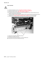 114
114 115
115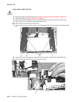 116
116 117
117 118
118 119
119 120
120 121
121 122
122 123
123

