LiftMaster BG790 BG790 Manual - Page 15
Low Voltage Circuit, General Reference Information, Primary Voltage Circuit - manual
 |
View all LiftMaster BG790 manuals
Add to My Manuals
Save this manual to your list of manuals |
Page 15 highlights
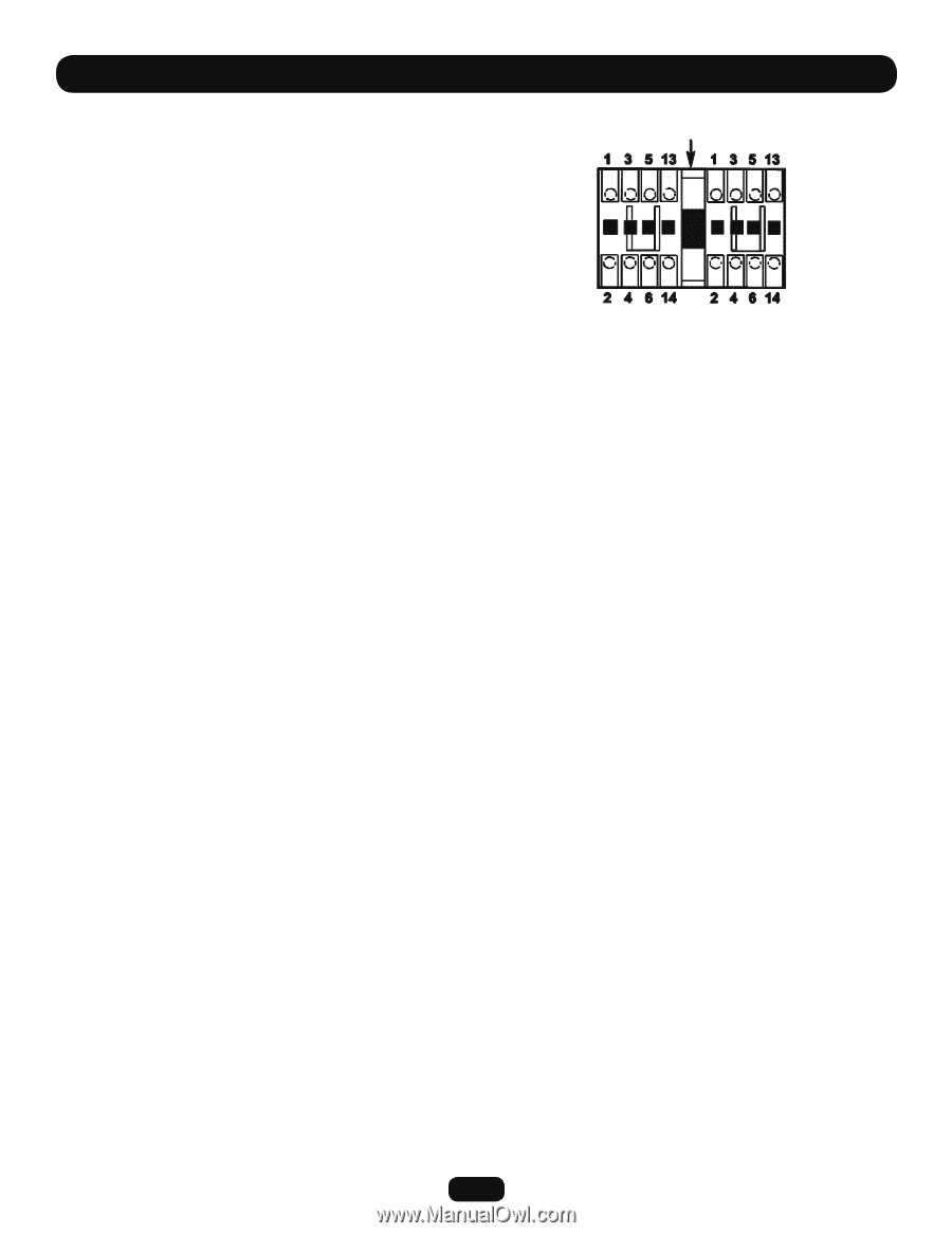
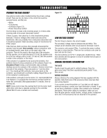
TROUBLESHOOTING PRIMARY VOLTAGE CIRCUIT Use extreme caution when troubleshooting the primary voltage circuit! There are five (4) items in this circuit that could be causing trouble, and they are: • Motor • Transformer • Contactor (Figure 13) • Power Disconnect Switch The first thing to check is the incoming power. Is it there at the incoming side of the power disconnect switch? If there is power, then check for it at the transformer primary terminals. If there is voltage at the switch and none at the transformer, then you probably have a bad power disconnect and it should be replaced. Check secondary output of transformer for 24Vac output. If the first two check out okay, then manually disconnect the operator from the gate. Very carefully, using a screwdriver with an insulated handle, press down on the open side of the contactor. Then do the same to the close side of the contactor. Did the operator run in both directions? If it did, the problem may be in the low voltage control circuit. It if did not, then the problem is either in the contactor or the motor. If the contactor is suspected to be causing the problem, first carefully check all wiring connections at the contacts (Figure 13). Disconnect Power! Using a volt-ohmmeter, take continuity readings across the contacts of the contactor. Remove wires from one side of the contactor. Place one probe on 1 and the other on 2. You should get NO continuity; now press down on the contactor; you should get a continuity reading. Repeat this on all of the contactor's contact points. If the problem is thought to be the motor, it is recommended that it be replaced. It is possible that the thermal overload inside the motor has overheated. Wait approximately 15 minutes, then try running unit. NOTE: Some motors have the overload built into the motor itself, while other units have a separate overload in the controller (Model BG770 uses a manual reset overload). Figure 13 Contactor LOW VOLTAGE CIRCUIT The first thing to check is the circuit breaker. The secondary voltage must be between 22 and 30Vac. This voltage can be checked at the circuit board at terminals 3 and 6. The contactor coils receive 24Vac. To activate the motor in either the open or close direction. There are two contactor coils (one for open and one for close). The limit switches are S.P.D.T. (single pole, double throw). These limit switches tell the operator to shut off at either the full open or full close position. GENERAL REFERENCE INFORMATION THE GATE Double check the gate and its related hardware. Does the gate move freely? Are there unprotected pinch points? If yes, then correct. WIRING DIAGRAM Always reference the wiring diagram that was supplied with the operator. Note that some of the accessory items may have their own wiring diagram. If you cannot correct the problem or if you feel you will require technical assistance, contact your local distributor or dealer. If you do not have a distributor or dealer, then contact us for technical assistance. Please when calling for assistance, make sure you have the gate operator model number, voltage, phase, horsepower and a list of all accessories that are attached to the operator. 15
-
 1
1 -
2
-
3
-
4
-
5
-
6
-
7
-
8
-
9
-
 10
10 -
 11
11 -
 12
12 -
 13
13 -
 14
14 -
 15
15 -
 16
16 -
 17
17 -
 18
18 -
 19
19 -
 20
20 -
21
-
22
-
23
-
24
 |
 |