LiftMaster BG790 BG790 Manual - Page 6
Installation - model
 |
View all LiftMaster BG790 manuals
Add to My Manuals
Save this manual to your list of manuals |
Page 6 highlights
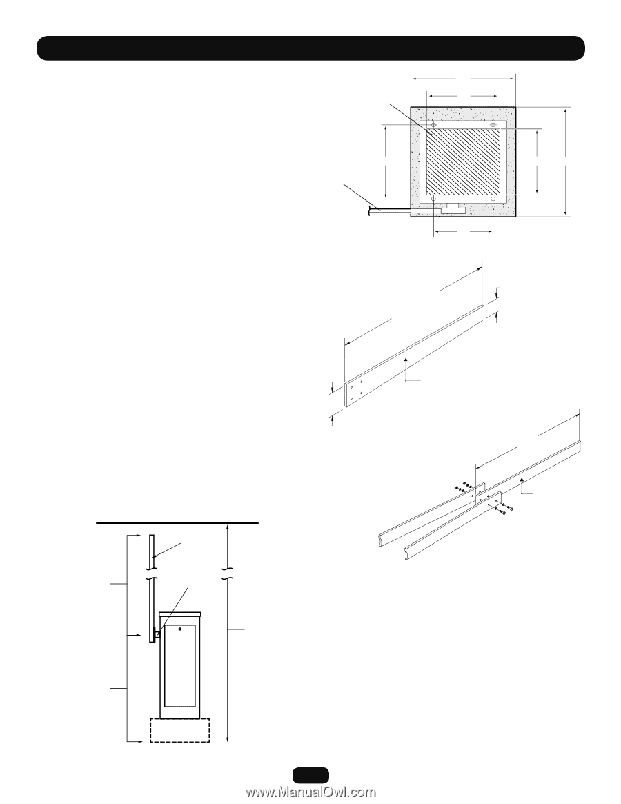
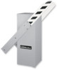
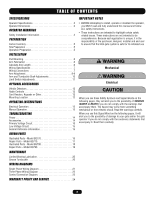
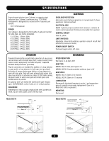
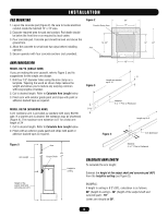
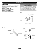
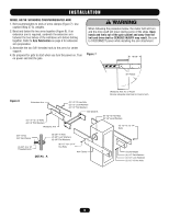
INSTALLATION PAD MOUNTING Figure 2 20" 1. Layout the concrete pad (Figure 2). Be sure to locate electrical Conduit Entry Area 14" conduit inside the hatched 14" x 13" area. 2. Excavate required area for pad and conduit. Pad depth should be below the frost line or as required by local codes. 3. Pour concrete pad. Concrete pad should be level and above the ground line. 14-1/2" 4. Allow the concrete to set at least two days before installing Arm operator. 5. Secure operator with four concrete anchors (not provided). 13" 22" ARM FABRICATION MODEL BG770 (SINGLE ARM) If you are making the arm yourself, refer to Figure 3 and its suggestions for the single arm design. 1. Drill four 1/2" diameter holes using the arm clamp as a template. Tapering the wood as shown helps reduce the weight and allows you to reduce any warping common with long lengths of lumber. 2. Cut to desired length. Refer to Calculate Arm Length below. 3. Finish arm with exterior grade paint and stripe with paint or adhesive backed tape as required. Figure 3 MODEL BG790 (WISHBONE ARM) 5-12" A 24' wishbone arm is provided as standard with every BG790 gate. If a shorter arm is desired, the extension may be shortened (Figure 4). The maximum arm extension is 8' for a total arm length of 24'. 1. Cut to desired length. Refer to Calculate Arm Length below. 2. Finish with an exterior grade paint and stripe with paint or adhesive backed tape as required. 12" 3" Length as needed up to 12' Material: 6: x 1" Pine or Redwood Length up to 8' Figure 4 Arm Extension Figure 5 Arm Material: 4: x 1" Pine or Redwood Arm length Height of the output shaft and concrete pad (40") Output Shaft Height to ceiling CALCULATE ARM LENGTH To calculate the arm length: Subtract the height of the output shaft and concrete pad (40") from the height to ceiling (see Figure 5). EXAMPLE: If height to ceiling is 8'3" (99"), calculation is as follows: 99" (height to ceiling) - 40" (height of the output shaft and concrete pad) = 59" Lower arm should be 59". 6
-
 1
1 -
 2
2 -
 3
3 -
 4
4 -
 5
5 -
 6
6 -
 7
7 -
 8
8 -
 9
9 -
 10
10 -
 11
11 -
 12
12 -
13
-
14
-
15
-
16
-
17
-
18
-
19
-
20
-
21
-
22
-
23
-
24
 |
 |