LiftMaster BG790 BG790 Manual - Page 9
Model Bg790: Wishbone Counterweighted Arm
 |
View all LiftMaster BG790 manuals
Add to My Manuals
Save this manual to your list of manuals |
Page 9 highlights
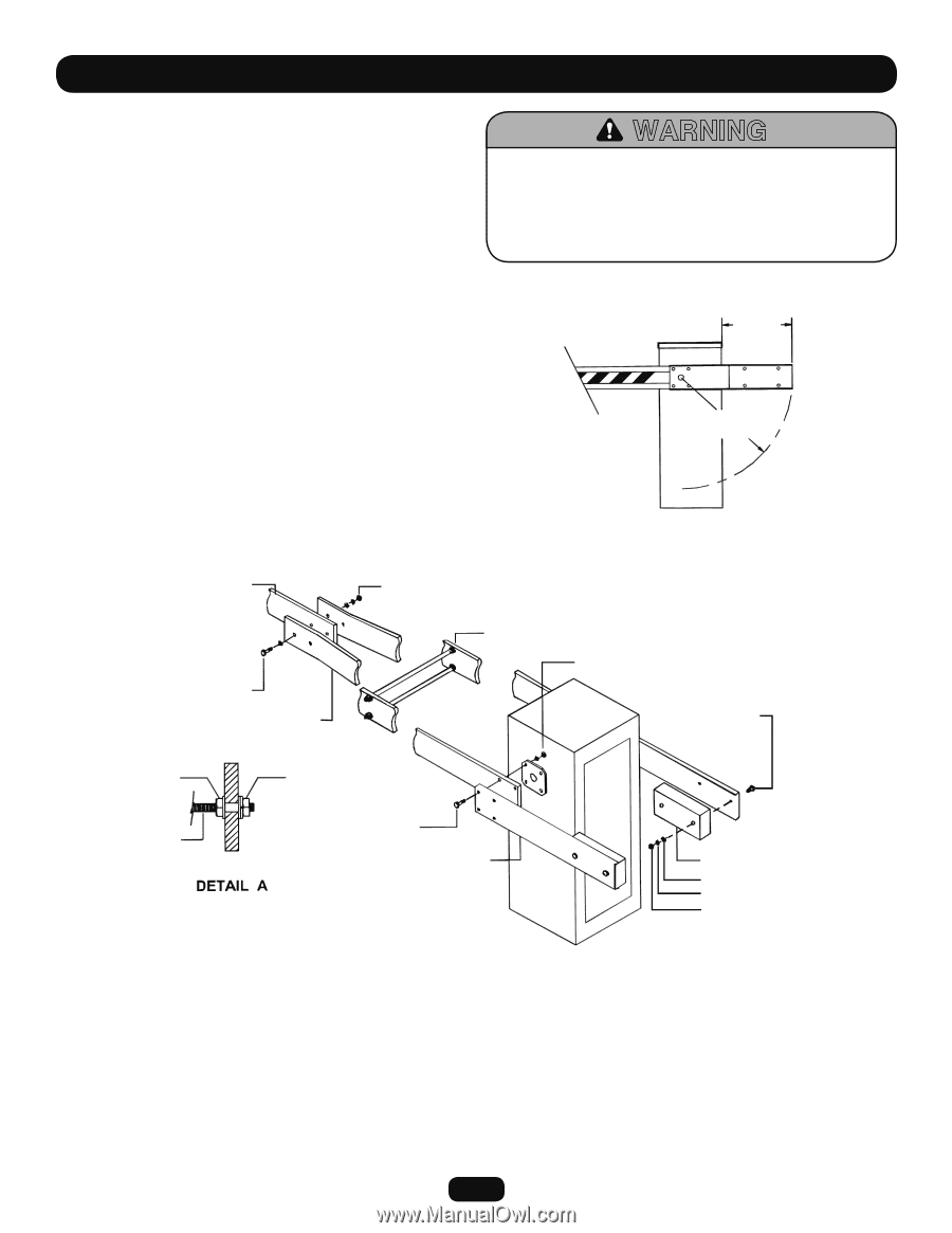
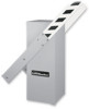
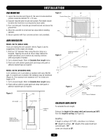
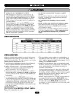
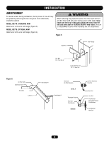
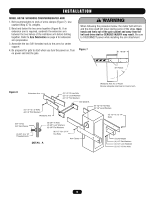
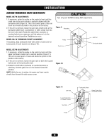
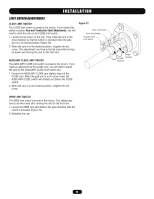
INSTALLATION MODEL BG790: WISHBONE COUNTERWEIGHTED ARM 1. Bolt counterweights to ends of arms clamps (Figure 7). Use caution lifting 57 lb. weights. 2. Bend and fasten the two arms together (Figure 8). If an extension arm is required, sandwich the extension arm between the two halves of the wishbone arm before bolting together. Refer to Arm Fabrication on page 6 for extension arm preparation. 3. Assemble the two 3/8" threaded rods to the arms for center support. 4. Be prepared for gate to start when you turn the power on. Turn on power and test the gate. WARNING When following the procedure below, the motor belt will turn and the drive shaft will move during some of the steps. Keep hands and tools out of the gate cabinet and away from the belt and drive shaft or SERIOUS INJURY may result. Be sure to DISCONNECT power while installing the arm attachment. Figure 7 18-5/8" 30" Radius Wishbone Arm Arc of Travel Ensure adequate clearance for travel of arm. Figure 8 Extension Arm (2) 1/2"-13 x 3" Bolts (2) 1/2" Flat Washers Wishbone Arm (2) 1/2"-13 Hex Nuts (2) 1/2" Lock Washers (2) 1/2" Flat Washers See Detail A (8) 1/2"-13 Hex Nuts (8) 1/2" Lock Washers (4) 1/2"-13 x 2-1/4" Bolts 3/8"-16 Nut 3/8" Flat Washer (2) 3/8"-16 x 18" Threaded Rods (8) 3/8"-16 Nuts (4) 3/8" Lock Washers (8) 3/8" Flat Washers (8) 1/2"-13 x 2-1/4" Hex Bolts Arm Clamp Counterweight (4) 1/2" Flat Washers (4) 1/2" Lock Washers (2) 1/2"-13 Hex Nuts 9
-
 1
1 -
2
-
3
-
 4
4 -
 5
5 -
 6
6 -
 7
7 -
 8
8 -
 9
9 -
 10
10 -
 11
11 -
 12
12 -
 13
13 -
 14
14 -
15
-
16
-
17
-
18
-
19
-
20
-
21
-
22
-
23
-
24
 |
 |