LiftMaster BG790 BG790 Manual - Page 2

Warning, Caution - gate

Page 2 highlights

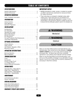
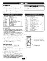
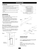
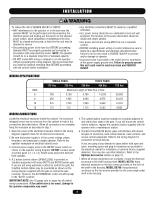
TABLE OF CONTENTS SPECIFICATIONS Operator Specifications 3 Operator Dimensions 3 OPERATOR WARNINGS Safety Installation Information 4 PREPARATION Carton Inventory 5 Site Preparation 5 Operation Preparation 5 INSTALLATION Pad Mounting 6 Arm Fabrication 6 Calculate Arm Length 6 Wiring Specifications 7 Wiring Connections 7 Arm Attachment 8-9 Arm and Turnbuckle Shaft Adjustments 10 Limit Switch Adjustments 11 OPTIONAL ACCESSORIES Vehicle Detectors 12 Radio Controls 12 Card Readers, Keypads or Other 12 Mounting Location 12 OPERATING INSTRUCTIONS Electrical Operation 13 Manual Operation 13 TROUBLESHOOTING Power 14 Accessories 14 Primary Voltage Circuit 15 Low Voltage Circuit 15 General Reference Information 15 REPAIR PARTS Illustrated Parts - Model BG770 16 Repair Parts - Model BG770 17 Illustrated Parts - Model BG790 18 Repair Parts - Model BG790 19 MAINTENANCE Limited Bearing Lubrication 20 Grease Turnbuckle 20 WIRING DIAGRAMS Single Phase Wiring Diagram 21 Three Phase Wiring Diagram 22 Control Connection Diagram 23 WARRANTY POLICY AND SERVICE 24 IMPORTANT NOTES • BEFORE attempting to install, operate or maintain the operator, you MUST read and fully understand this manual and follow ALL safety instructions. • These instructions are intended to highlight certain safety related issues. These instructions are not intended to be comprehensive. Because each application is unique, it is the responsibility of the purchaser, designer, installer and end user to ensure that the total gate system is safe for its intended use WARNING Mechanical WARNING Electrical CAUTION When you see these Safety Symbols and Signal Words on the following pages, they will alert you to the possibility of SERIOUS INJURY or DEATH if you do not comply with the warnings that accompany them. The hazard may come from something mechanical or from electric shock. Read the warnings carefully. When you see this Signal Word on the following pages, it will alert you to the possibility of damage to your gate and/or the gate operator if you do not comply with the cautionary statements that accompany it. Read them carefully. 2

  • 1
  • 2
  • 3
  • 4
  • 5
  • 6
  • 7
  • 8
  • 9
  • 10
  • 11
  • 12
  • 13
  • 14
  • 15
  • 16
  • 17
  • 18
  • 19
  • 20
  • 21
  • 22
  • 23
  • 24

2
SPECIFICATIONS
Operator Specifications. . . . . . . . . . . . . . . . . . . . . . . . . . . . . . . . .3
Operator Dimensions
. . . . . . . . . . . . . . . . . . . . . . . . . . . . . . . . . .3
OPERATOR WARNINGS
Safety Installation Information . . . . . . . . . . . . . . . . . . . . . . . . . . .4
PREPARATION
Carton Inventory. . . . . . . . . . . . . . . . . . . . . . . . . . . . . . . . . . . . . .5
Site Preparation
. . . . . . . . . . . . . . . . . . . . . . . . . . . . . . . . . . . . . .5
Operation Preparation. . . . . . . . . . . . . . . . . . . . . . . . . . . . . . . . . .5
INSTALLATION
Pad Mounting . . . . . . . . . . . . . . . . . . . . . . . . . . . . . . . . . . . . . . . . 6
Arm Fabrication
. . . . . . . . . . . . . . . . . . . . . . . . . . . . . . . . . . . . . .6
Calculate Arm Length . . . . . . . . . . . . . . . . . . . . . . . . . . . . . . . . . .6
Wiring Specifications
. . . . . . . . . . . . . . . . . . . . . . . . . . . . . . . . . .7
Wiring Connections
. . . . . . . . . . . . . . . . . . . . . . . . . . . . . . . . . . .7
Arm Attachment . . . . . . . . . . . . . . . . . . . . . . . . . . . . . . . . . . . . 8-9
Arm and Turnbuckle Shaft Adjustments . . . . . . . . . . . . . . . . . . . 10
Limit Switch Adjustments. . . . . . . . . . . . . . . . . . . . . . . . . . . . . .11
OPTIONAL ACCESSORIES
Vehicle Detectors
. . . . . . . . . . . . . . . . . . . . . . . . . . . . . . . . . . . .12
Radio Controls
. . . . . . . . . . . . . . . . . . . . . . . . . . . . . . . . . . . . . .12
Card Readers, Keypads or Other. . . . . . . . . . . . . . . . . . . . . . . . .12
Mounting Location . . . . . . . . . . . . . . . . . . . . . . . . . . . . . . . . . . .12
OPERATING INSTRUCTIONS
Electrical Operation. . . . . . . . . . . . . . . . . . . . . . . . . . . . . . . . . . .13
Manual Operation . . . . . . . . . . . . . . . . . . . . . . . . . . . . . . . . . . . .13
TROUBLESHOOTING
Power . . . . . . . . . . . . . . . . . . . . . . . . . . . . . . . . . . . . . . . . . . . . .14
Accessories. . . . . . . . . . . . . . . . . . . . . . . . . . . . . . . . . . . . . . . . .14
Primary Voltage Circuit. . . . . . . . . . . . . . . . . . . . . . . . . . . . . . . .15
Low Voltage Circuit. . . . . . . . . . . . . . . . . . . . . . . . . . . . . . . . . . .15
General Reference Information . . . . . . . . . . . . . . . . . . . . . . . . . . 15
REPAIR PARTS
Illustrated Parts - Model BG770 . . . . . . . . . . . . . . . . . . . . . . . . . 16
Repair Parts - Model BG770. . . . . . . . . . . . . . . . . . . . . . . . . . . .17
Illustrated Parts - Model BG790 . . . . . . . . . . . . . . . . . . . . . . . . . 18
Repair Parts - Model BG790. . . . . . . . . . . . . . . . . . . . . . . . . . . .19
MAINTENANCE
Limited Bearing Lubrication . . . . . . . . . . . . . . . . . . . . . . . . . . . .20
Grease Turnbuckle
. . . . . . . . . . . . . . . . . . . . . . . . . . . . . . . . . . .20
WIRING DIAGRAMS
Single Phase Wiring Diagram . . . . . . . . . . . . . . . . . . . . . . . . . . . 21
Three Phase Wiring Diagram
. . . . . . . . . . . . . . . . . . . . . . . . . . .22
Control Connection Diagram. . . . . . . . . . . . . . . . . . . . . . . . . . . .23
WARRANTY POLICY AND SERVICE
. . . . . . . . . . . . . . . . 24
TABLE OF CONTENTS
Mechanical
Electrical
WARNING
CAUTION
WARNING
When you see these Safety Symbols and Signal Words on the
following pages, they will alert you to the possibility of
SERIOUS
INJURY or DEATH
if you do not comply with the warnings that
accompany them. The hazard may come from something
mechanical or from electric shock. Read the warnings carefully.
When you see this Signal Word on the following pages, it will
alert you to the possibility of damage to your gate and/or the gate
operator if you do not comply with the cautionary statements that
accompany it. Read them carefully.
IMPORTANT NOTES
BEFORE attempting to install, operate or maintain the operator,
you MUST read and fully understand this manual and follow
ALL safety instructions.
These instructions are intended to highlight certain safety
related issues. These instructions are not intended to be
comprehensive. Because each application is unique, it is the
responsibility of the purchaser, designer, installer and end user
to ensure that the total gate system is safe for its intended use