LiftMaster BG790 BG790 Manual - Page 5
Warning - operator
 |
View all LiftMaster BG790 manuals
Add to My Manuals
Save this manual to your list of manuals |
Page 5 highlights
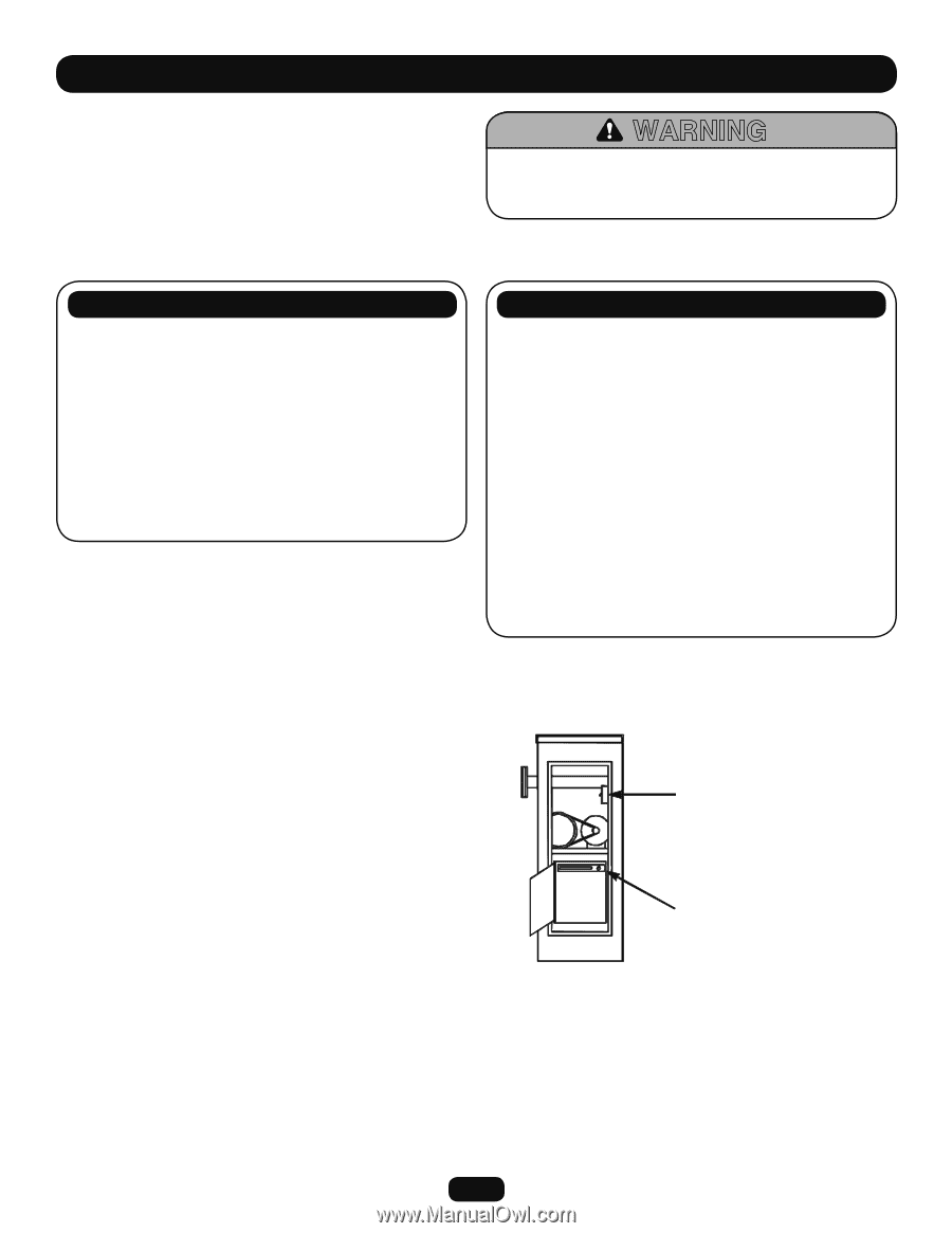
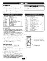
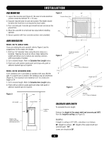
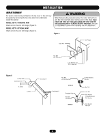
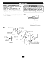
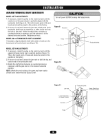
PREPARATIONS CARTON INVENTORY 1. Unpack the carton, checking for possible damage during shipping. The arm (when provided) is packed separately. Damage claims MUST be filed with the freight carrier. 2. Check that the nameplate data (inside service cover) accurately matches the operator that was ordered. 3. Verify that the following parts are included with the standard unit. WARNING To reduce the risk of SEVERE INJURY or DEATH, disconnect power BEFORE performing ANY adjustments. MODEL BG770 PACKING LIST PART NUMBER DESCRIPTION QTY 02-102 Open/Close Push Button 1 07-8007 Gate Arm Hub 1 10-8007M Gate Bracket 1 80-G0187 Key, 1/2 x 1/2 x 1-3/8 1 82-NH38-06 Cone Point Set Screw, 3/8-16 x 3/8 2 82-HN50-25 Hex Bolt, 1/2-13 x 2-1/4 4 82-RH-50 Hex Nut, 1/2-13 4 85-LS-50 Split Lock Washer, 1/2 4 01-G0674 Owner's Manual 1 SITE PREPARATION 1. Be sure that selected gate location has required clearance for arm movement (and counterweights on model BG790). Refer to the dimensional drawings on page 3. 2. Run electrical power to the site according to local electrical codes (Figure 1). See chart on page 7 for correct wire size and length of run. If the wire gauge is too high (wire too small) or the run is too long, the gate may not run properly or may not run at all. Damage to components may result. IMPORTANT NOTE: Be sure that the available power is the proper voltage, phase, frequency, and amperage to supply the gate. Refer to gate nameplate located inside the service cover. 3. Select locations for control equipment and run any control wiring that may be needed (such as loop wires, card readers, ticket spitters, pushbuttons, etc.). MODEL BG790 PACKING LIST PART NUMBER DESCRIPTION QTY 02-102 Open/Close Push Button 1 07-8007 Arm Hub 2 10-8055 Counter Weight Clamp 2 80-G0135 Threaded Rod, 3/8-16 x 18 2 80-G0187 Key, 1/2 x 1/2 x 1-3/8 2 82-HN50-25 Hex Head Bolt, 1/2-13 x 2-1/4 12 82-HN50-28 Hex Head Bolt, 1/2-13 x 3 2 82-NH38-06 Cone Point Set Screw, 3/8-16 x 3/8 4 84-RH-50 Hex Nut, 1/2-13 14 84-WH-38 Serrated Flange Nut, 3/8-16 8 85-FW-38 Flat Washer, 3/8 8 85-FW-50 Flat Washer, 1/2 8 85-LS-50 Split Lock Washer, 1/2 16 01-G0674 Owner's Manual 1 Figure 1 NOTE: Install line power here. Do not install line power in panel shown below. Power switch should be in the OFF position. OPERATOR PREPARATION 1. Remove the wood base from the unit and discard. 2. Locate the keys for the access panel (taped to the arm mounting flange) and remove. 3. Open the side access panel and check the position of the power ON/OFF switch. 4. Open the cover of the electrical cabinet and be sure that the AUTO/MANUAL switch is in the "AUTO" position. 5. OPTIONAL CONTROL EQUIPMENT: If loop detectors, radio controls, or other control equipment will be added at the site, do so now. Refer to the instructions in this manual for installation of factory-provided optional open and/or hold open loop detectors and for connection of factory-provided optional radio controls (see Optional Accessories on page 12). 5 AUTO/MANUAL switch should be in the "AUTO" position.
-
 1
1 -
 2
2 -
 3
3 -
 4
4 -
 5
5 -
 6
6 -
 7
7 -
 8
8 -
 9
9 -
 10
10 -
 11
11 -
12
-
13
-
14
-
15
-
16
-
17
-
18
-
19
-
20
-
21
-
22
-
23
-
24
 |
 |