LiftMaster CAPAC Installation Manual - English French Spanish - Page 13
Mounting/Power, shown below perpendicular to each other.
 |
View all LiftMaster CAPAC manuals
Add to My Manuals
Save this manual to your list of manuals |
Page 13 highlights
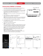
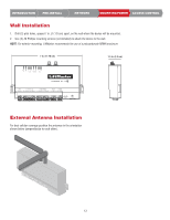
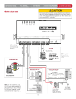
INTRODUCTION PRE-INSTALL NETWORK MOUNTING/POWER ACCESS CONTROL Wall Installation 1. Drill (2) pilot holes, spaced 7 in. (17.78 cm) apart, on the wall where the device will be mounted. 2. Use (2) #6 Phillips mounting screws (not included) to attach the device to the wall. NOTE: For exterior mounting, LiftMaster recommends the use of a polycarbonate NEMA enclosure. 7 in. (17.78 cm) 1.3 in. (3.3 cm) OUTPUT WIEGAND INPUT GATE 1 OUTPUT 2 SDA SCL NO COM NC NO COM NC 1 WIEGAND 2 D1 COM D0 D1 COM D0 INPUT POWER 1 GND 2 GND 12V-24V POWER ETHERNET External Antenna Installation For best cellular coverage position the antennas in the orientation shown below (perpendicular to each other). 13
-
 1
1 -
2
-
3
-
4
-
5
-
6
-
7
-
 8
8 -
 9
9 -
 10
10 -
 11
11 -
 12
12 -
 13
13 -
 14
14 -
 15
15 -
 16
16 -
 17
17 -
 18
18 -
19
-
20
-
21
-
22
-
23
-
24
-
25
-
26
-
27
-
28
-
29
-
30
-
31
-
32
-
33
-
34
-
35
-
36
-
37
-
38
-
39
-
40
-
41
-
42
-
43
-
44
-
45
-
46
-
47
-
48
-
49
-
50
-
51
-
52
-
53
-
54
-
55
-
56
-
57
-
58
-
59
-
60
 |
 |

13
ACCESS CONTROL
MOUNTING/POWER
NETWORK
PRE-INSTALL
INTRODUCTION
Wall Installation
External Antenna Installation
1.
Drill (2) pilot holes, spaced 7 in. (17.78 cm) apart, on the wall where the device will be mounted.
2.
Use (2) #6 Phillips mounting screws (not included) to attach the device to the wall.
NOTE
: For exterior mounting, LiftMaster recommends the use of a polycarbonate NEMA enclosure.
For best cellular coverage position the antennas in the orientation
shown below (perpendicular to each other).
INPUT
OUTPUT
WIEGAND
GATE
SDA SCL
OUTPUT
NO COM NC
NO COM NC
1
2
D1 COM D0
D1 COM D0
1
2
WIEGAND
1
GND
2
INPUT
GND 12V-24V
POWER
POWER
ETHERNET
7 in. (17.78 cm)
1.3 in. (3.3 cm)